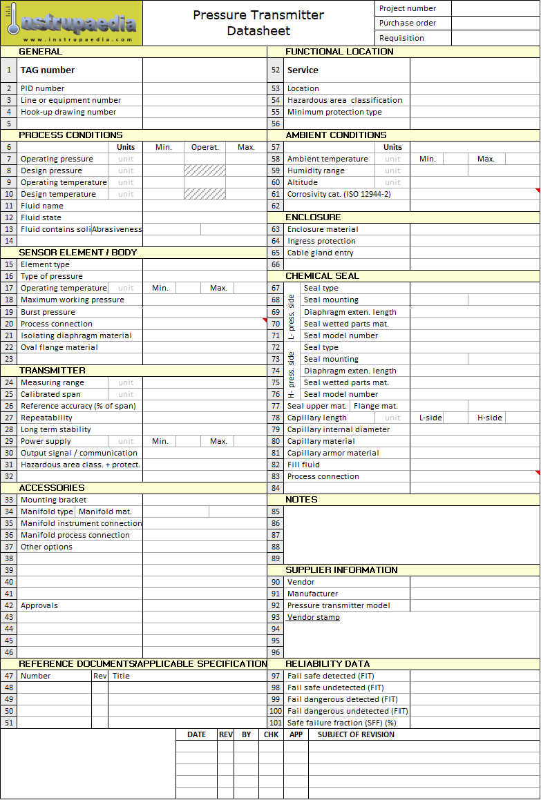
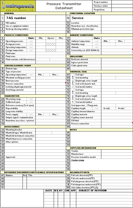
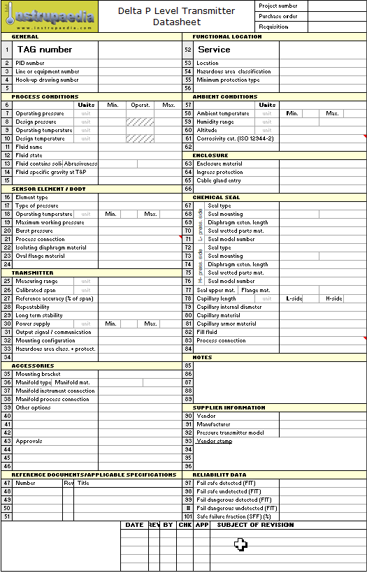
This datasheet template can specify pressure transmitters for measuring absolute, relative, or differential pressure using a resistive, piezo-resistive, piezo-electric, capacitive, or silicon resonant sensor.
Click once on the download button to download the datasheet in Excel format. If you prefer to first have a look at it in PDF, click the template image below. Further instructions for downloading and using this template are at the bottom of this page.
Notice Instrupaedia has no link whatsoever with an existing manufacturer or supplier of this type of device, nor do we receive any commission on the use of this datasheet template. The only objective is to help you specify and order your material. You can fill in the datasheet template and send it to any supplier of pressure gauges you want.
The Excel file will be sent to your device after pressing the download button. If you do this from a computer or an Android phone, the file will end up in your download folder. From there you can open it by double-clicking on the file. Of course, you must have Microsoft Excel 2007 or later installed.
To perform a download to an iPhone or an iPad, tap on the download button of the desired datasheet. Then tap on the Share button and select the location where you want to save the file. This could be your Download folder, Dropbox or iCloud service. Now, tap the Save button and you’re done. To open the datasheet, you must first install a spreadsheet program on your device. In the app store, you can find programs like Numbers (Apple) or Microsoft Excel (Microsoft). Please note that these apps are not free. After the download, you can then open the file with your spreadsheet app.
The full functionality will not be available on a smartphone or a tablet. To be able to use all of the features of this datasheet, it is best to open it with Microsoft Excel 2007 or later via a laptop or desktop computer.
Instructions for using the template
Layout of the datasheet template
The template is divided into several blocks, with each block containing related information. For example, there is a block with information about the process conditions, another about the sensor element, or yet another about the enclosure …
Each block contains cells on the left with a description of a property on which a choice must be entered in the cells on the right.
Drop-down lists
For many of these cells, a choice can be made from a drop-down list. To do this, first click in the cell and then on the small triangle to the right of the cell. Make a choice from the list and select this choice by clicking on it. Your choice will be automatically entered in the selected cell. With the help of the drop-down lists, you can easily find the right technical term for the desired property.
Some cells do not have a drop-down list because the information that must be entered has endless possibilities. These cells have to be entered directly.
Error messages
The suggested choices from the drop-down lists correspond to what is available from most suppliers. If you think you need something else, you can enter the cell directly without making a choice from the list. However, some cells cannot be entered directly. This is to prevent you from entering something wrong. If you do it anyway, you will receive an error message with explanatory text. There are error messages that you can override and others that oblige you to make a choice from the drop-down list.
Comment blocks
Cells with a red triangle in the upper right corner open up a comment block when you hover over it. The comment relates to what you can enter in the cell or provides an explanation of the possible choices, so you will fully understand the impact of your choice.
Input messages
Every cell that has a drop-down list or a comment block also shows an input message when the cell is clicked. The input message appears in a rectangle below the cell and indicates whether you are obliged to choose from the list or whether you can enter something else. Sometimes the message also gives an extra tip.
Company logo
If you like you can put your own company name or logo in the bottom-left cell of the title block.
Although you can remove the Instrupaedia logo, please be so kind to leave it in so other people who receive this datasheet could also find it on the web and use it to their benefit too.
“Suggestions to improve this datasheet are always welcome.”
“If you think something needs to be changed, deleted or added, please leave a comment in the comments section below.”
Advertisement
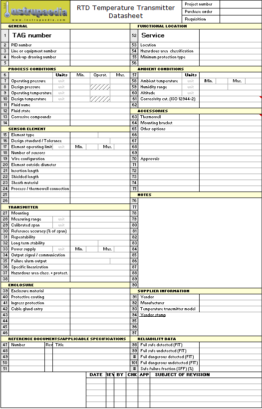
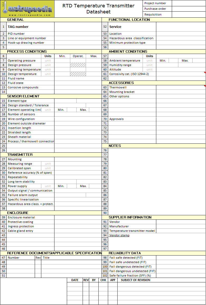
RTD temperature transmitter datasheet
This datasheet template can specify Pt100 or Pt1000 temperature transmitters with a wire-wound, a thin-film, or a coiled sensor.
Click once on the download button to download the datasheet in Excel format. If you prefer to first have a look at it in PDF, click the template image below. Further instructions for downloading and using this template are at the bottom of this page.
Notice Instrupaedia has no link whatsoever with an existing manufacturer or supplier of this type of device, nor do we receive any commission on the use of this datasheet template. The only objective is to help you specify and order your material. You can fill in the datasheet template and send it to any supplier of pressure gauges you want.
Customizable RTD temperature transmitter datasheet
The Excel file will be sent to your device after pressing the download button. If you do this from a computer or an Android phone, the file will end up in your download folder. From there you can open it by double-clicking on the file. Of course, you must have Microsoft Excel 2007 or later installed.
To perform a download to an iPhone or an iPad, tap on the download button of the desired datasheet. Then tap on the Share button and select the location where you want to save the file. This could be your Download folder, Dropbox or iCloud service. Now, tap the Save button and you’re done. To open the datasheet, you must first install a spreadsheet program on your device. In the app store, you can find programs like Numbers (Apple) or Microsoft Excel (Microsoft). Please note that these apps are not free. After the download, you can then open the file with your spreadsheet app.
The full functionality will not be available on a smartphone or a tablet. To be able to use all of the features of this datasheet, it is best to open it with Microsoft Excel 2007 or later via a laptop or desktop computer.
Instructions for using the template
Layout of the datasheet template
The template is divided into several blocks, with each block containing related information. For example, there is a block with information about the process conditions, another about the sensor element, or yet another about the enclosure …
Each block contains cells on the left with a description of a property on which a choice must be entered in the cells on the right.
Drop-down lists
For many of these cells, a choice can be made from a drop-down list. To do this, first click in the cell and then on the small triangle to the right of the cell. Make a choice from the list and select this choice by clicking on it. Your choice will be automatically entered in the selected cell. With the help of the drop-down lists, you can easily find the right technical term for the desired property.
Some cells do not have a drop-down list because the information that must be entered has endless possibilities. These cells have to be entered directly.
Error messages
The suggested choices from the drop-down lists correspond to what is available from most suppliers. If you think you need something else, you can enter the cell directly without making a choice from the list. However, some cells cannot be entered directly. This is to prevent you from entering something wrong. If you do it anyway, you will receive an error message with explanatory text. There are error messages that you can override and others that oblige you to make a choice from the drop-down list.
Comment blocks
Cells with a red triangle in the upper right corner open up a comment block when you hover over it. The comment relates to what you can enter in the cell or provides an explanation of the possible choices, so you will fully understand the impact of your choice.
Input messages
Every cell that has a drop-down list or a comment block also shows an input message when the cell is clicked. The input message appears in a rectangle below the cell and indicates whether you are obliged to choose from the list or whether you can enter something else. Sometimes the message also gives an extra tip.
Company logo
If you like you can put your own company name or logo in the bottom-left cell of the title block.
Although you can remove the Instrupaedia logo, please be so kind to leave it in so other people who receive this datasheet could also find it on the web and use it to their benefit too.
“Suggestions to improve this datasheet are always welcome.”
“If you think something needs to be changed, deleted or added, please leave a comment in the comments section below.”
Advertisement
Bimetal thermometer datasheet
Specification sheet templates for Excel and pdf
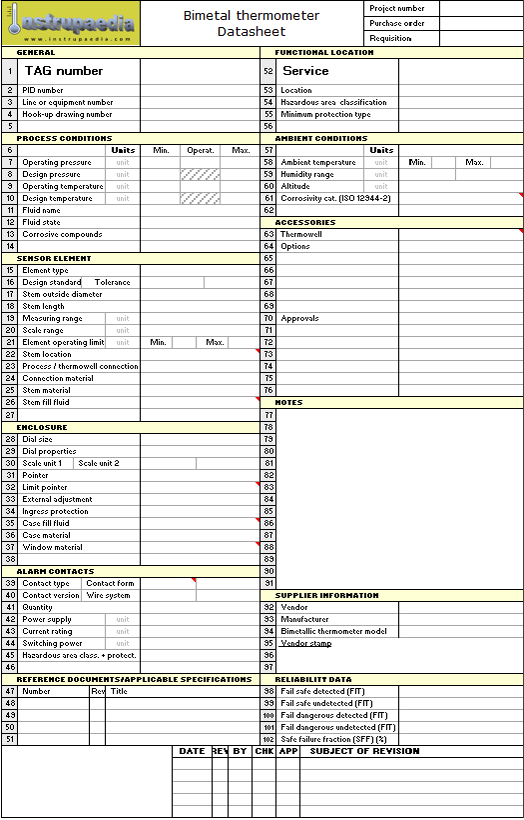
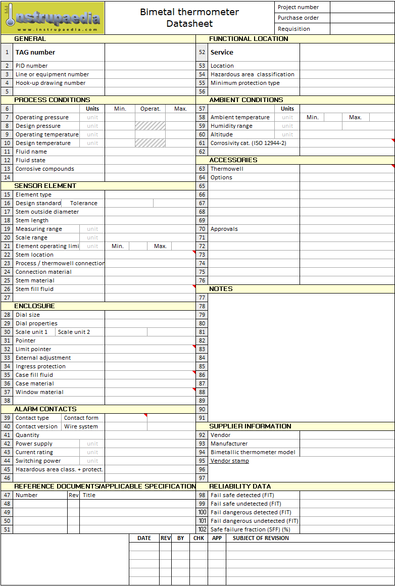
This datasheet can specify thermometers with a single or double helix bimetal temperature sensor and electrical alarm contacts.
Click once on the download button to download the datasheet in Excel format. If you prefer to first have a look at it in PDF, click the template image below. Further instructions for downloading and using this template are at the bottom of this page.
Notice Instrupaedia has no link whatsoever with an existing manufacturer or supplier of this type of device, nor do we receive any commission on the use of this datasheet template. The only objective is to help you specify and order your material. You can fill in the datasheet template and send it to any supplier of pressure gauges you want.
The Excel file will be sent to your device after pressing the download button. If you do this from a computer or an Android phone, the file will end up in your download folder. From there you can open it by double-clicking on the file. Of course, you must have Microsoft Excel 2007 or later installed.
To perform a download to an iPhone or an iPad, tap on the download button of the desired datasheet. Then tap on the Share button and select the location where you want to save the file. This could be your Download folder, Dropbox or iCloud service. Now, tap the Save button and you’re done. To open the datasheet, you must first install a spreadsheet program on your device. In the app store, you can find programs like Numbers (Apple) or Microsoft Excel (Microsoft). Please note that these apps are not free. After the download, you can then open the file with your spreadsheet app.
The full functionality will not be available on a smartphone or a tablet. To be able to use all of the features of this datasheet, it is best to open it with Microsoft Excel 2007 or later via a laptop or desktop computer.
Instructions for using the template
Layout of the datasheet template
The template is divided into several blocks, with each block containing related information. For example, there is a block with information about the process conditions, another about the sensor element, or yet another about the enclosure …
Each block contains cells on the left with a description of a property on which a choice must be entered in the cells on the right.
Drop-down lists
For many of these cells, a choice can be made from a drop-down list. To do this, first click in the cell and then on the small triangle to the right of the cell. Make a choice from the list and select this choice by clicking on it. Your choice will be automatically entered in the selected cell. With the help of the drop-down lists, you can easily find the right technical term for the desired property.
Some cells do not have a drop-down list because the information that must be entered has endless possibilities. These cells have to be entered directly.
Error messages
The suggested choices from the drop-down lists correspond to what is available from most suppliers. If you think you need something else, you can enter the cell directly without making a choice from the list. However, some cells cannot be entered directly. This is to prevent you from entering something wrong. If you do it anyway, you will receive an error message with explanatory text. There are error messages that you can override and others that oblige you to make a choice from the drop-down list.
Comment blocks
Cells with a red triangle in the upper right corner open up a comment block when you hover over it. The comment relates to what you can enter in the cell or provides an explanation of the possible choices, so you will fully understand the impact of your choice.
Input messages
Every cell that has a drop-down list or a comment block also shows an input message when the cell is clicked. The input message appears in a rectangle below the cell and indicates whether you are obliged to choose from the list or whether you can enter something else. Sometimes the message also gives an extra tip.
Company logo
If you like you can put your own company name or logo in the bottom-left cell of the title block.
Although you can remove the Instrupaedia logo, please be so kind to leave it in so other people who receive this datasheet could also find it on the web and use it to their benefit too.
“Suggestions to improve this datasheet are always welcome.”
“If you think something needs to be changed, deleted or added, please leave a comment in the comments section below.”
Advertisement
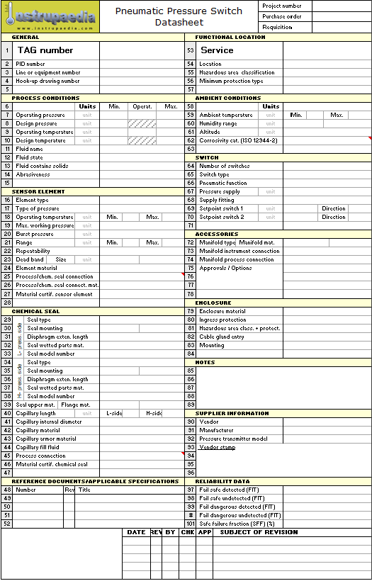
Pneumatic pressure switch datasheet
Specification sheet templates for Excel and pdf
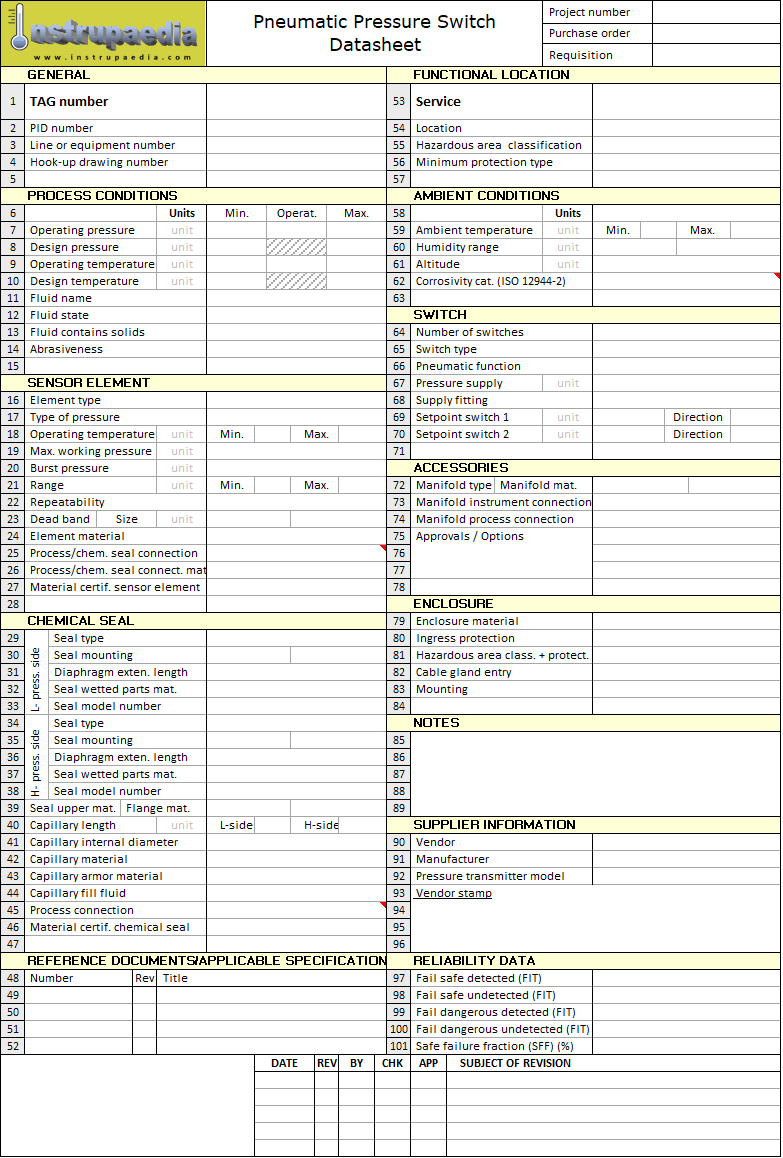
This datasheet template can specify pressure switches with a pneumatic output contact and a pressure sensing element such as a bellows, a Bourdon tube, a diaphragm, or a piston.
Click once on the download button to download the datasheet in Excel format. If you prefer to first have a look at it in PDF, click the template image below. Further instructions for downloading and using this template are at the bottom of this page.
Notice Instrupaedia has no link whatsoever with an existing manufacturer or supplier of this type of device, nor do we receive any commission on the use of this datasheet template. The only objective is to help you specify and order your material. You can fill in the datasheet template and send it to any supplier of pressure gauges you want.
The Excel file will be sent to your device after pressing the download button. If you do this from a computer or an Android phone, the file will end up in your download folder. From there you can open it by double-clicking on the file. Of course, you must have Microsoft Excel 2007 or later installed.
To perform a download to an iPhone or an iPad, tap on the download button of the desired datasheet. Then tap on the Share button and select the location where you want to save the file. This could be your Download folder, Dropbox or iCloud service. Now, tap the Save button and you’re done. To open the datasheet, you must first install a spreadsheet program on your device. In the app store, you can find programs like Numbers (Apple) or Microsoft Excel (Microsoft). Please note that these apps are not free. After the download, you can then open the file with your spreadsheet app.
The full functionality will not be available on a smartphone or a tablet. To be able to use all of the features of this datasheet, it is best to open it with Microsoft Excel 2007 or later via a laptop or desktop computer.
Instructions for using the template
Layout of the datasheet template
The template is divided into several blocks, with each block containing related information. For example, there is a block with information about the process conditions, another about the sensor element, or yet another about the enclosure …
Each block contains cells on the left with a description of a property on which a choice must be entered in the cells on the right.
Drop-down lists
For many of these cells, a choice can be made from a drop-down list. To do this, first click in the cell and then on the small triangle to the right of the cell. Make a choice from the list and select this choice by clicking on it. Your choice will be automatically entered in the selected cell. With the help of the drop-down lists, you can easily find the right technical term for the desired property.
Some cells do not have a drop-down list because the information that must be entered has endless possibilities. These cells have to be entered directly.
Error messages
The suggested choices from the drop-down lists correspond to what is available from most suppliers. If you think you need something else, you can enter the cell directly without making a choice from the list. However, some cells cannot be entered directly. This is to prevent you from entering something wrong. If you do it anyway, you will receive an error message with explanatory text. There are error messages that you can override and others that oblige you to make a choice from the drop-down list.
Comment blocks
Cells with a red triangle in the upper right corner open up a comment block when you hover over it. The comment relates to what you can enter in the cell or provides an explanation of the possible choices, so you will fully understand the impact of your choice.
Input messages
Every cell that has a drop-down list or a comment block also shows an input message when the cell is clicked. The input message appears in a rectangle below the cell and indicates whether you are obliged to choose from the list or whether you can enter something else. Sometimes the message also gives an extra tip.
Company logo
If you like you can put your own company name or logo in the bottom-left cell of the title block.
Although you can remove the Instrupaedia logo, please be so kind to leave it in so other people who receive this datasheet could also find it on the web and use it to their benefit too.
“Suggestions to improve this datasheet are always welcome.”
“If you think something needs to be changed, deleted or added, please leave a comment in the comments section below.”
Advertisement
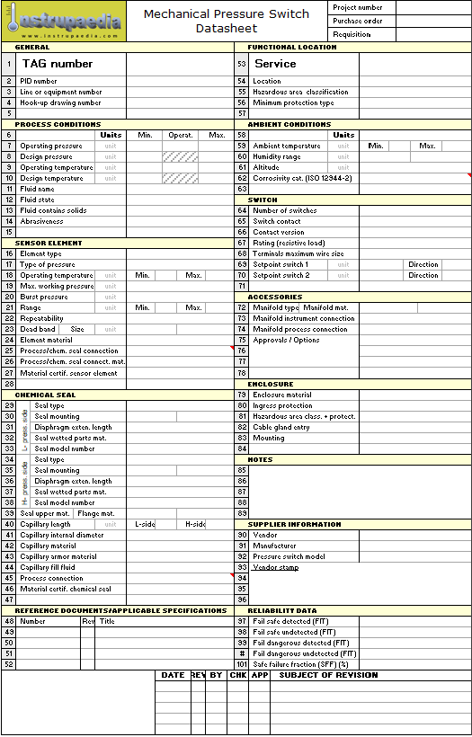
Mechanical pressure switch datasheet
Specification sheet templates for Excel and pdf
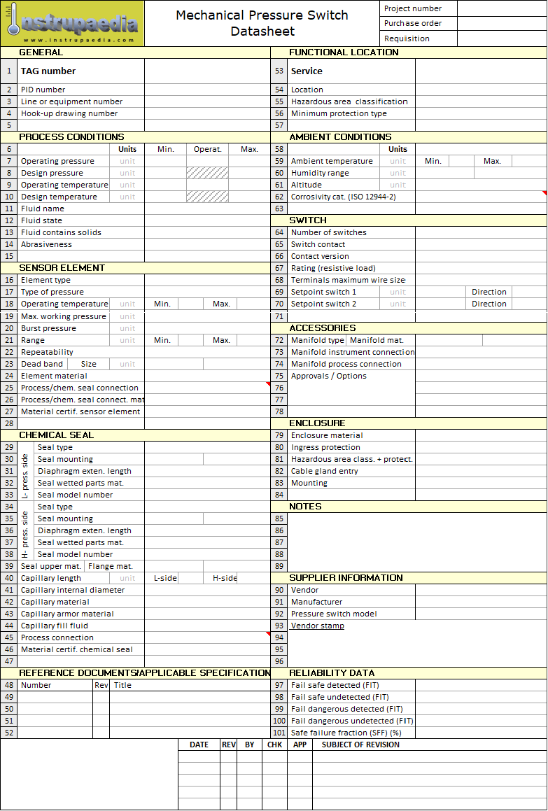
This datasheet template can specify pressure switches with an electrical SPDT or DPDT output contact and pressure-sensitive elements such as a bellows, a Bourdon tube, a diaphragm, or a piston.
Click once on the download button to download the datasheet in Excel format. If you prefer to first have a look at it in PDF, click the template image below. Further instructions for downloading and using this template are at the bottom of this page.
Notice Instrupaedia has no link whatsoever with an existing manufacturer or supplier of this type of device, nor do we receive any commission on the use of this datasheet template. The only objective is to help you specify and order your material. You can fill in the datasheet template and send it to any supplier of pressure gauges you want.
The Excel file will be sent to your device after pressing the download button. If you do this from a computer or an Android phone, the file will end up in your download folder. From there you can open it by double-clicking on the file. Of course, you must have Microsoft Excel 2007 or later installed.
To perform a download to an iPhone or an iPad, tap on the download button of the desired datasheet. Then tap on the Share button and select the location where you want to save the file. This could be your Download folder, Dropbox or iCloud service. Now, tap the Save button and you’re done. To open the datasheet, you must first install a spreadsheet program on your device. In the app store, you can find programs like Numbers (Apple) or Microsoft Excel (Microsoft). Please note that these apps are not free. After the download, you can then open the file with your spreadsheet app.
The full functionality will not be available on a smartphone or a tablet. To be able to use all of the features of this datasheet, it is best to open it with Microsoft Excel 2007 or later via a laptop or desktop computer.
Instructions for using the template
Layout of the datasheet template
The template is divided into several blocks, with each block containing related information. For example, there is a block with information about the process conditions, another about the sensor element, or yet another about the enclosure …
Each block contains cells on the left with a description of a property on which a choice must be entered in the cells on the right.
Drop-down lists
For many of these cells, a choice can be made from a drop-down list. To do this, first click in the cell and then on the small triangle to the right of the cell. Make a choice from the list and select this choice by clicking on it. Your choice will be automatically entered in the selected cell. With the help of the drop-down lists, you can easily find the right technical term for the desired property.
Some cells do not have a drop-down list because the information that must be entered has endless possibilities. These cells have to be entered directly.
Error messages
The suggested choices from the drop-down lists correspond to what is available from most suppliers. If you think you need something else, you can enter the cell directly without making a choice from the list. However, some cells cannot be entered directly. This is to prevent you from entering something wrong. If you do it anyway, you will receive an error message with explanatory text. There are error messages that you can override and others that oblige you to make a choice from the drop-down list.
Comment blocks
Cells with a red triangle in the upper right corner open up a comment block when you hover over it. The comment relates to what you can enter in the cell or provides an explanation of the possible choices, so you will fully understand the impact of your choice.
Input messages
Every cell that has a drop-down list or a comment block also shows an input message when the cell is clicked. The input message appears in a rectangle below the cell and indicates whether you are obliged to choose from the list or whether you can enter something else. Sometimes the message also gives an extra tip.
Company logo
If you like you can put your own company name or logo in the bottom-left cell of the title block.
Although you can remove the Instrupaedia logo, please be so kind to leave it in so other people who receive this datasheet could also find it on the web and use it to their benefit too.
“Suggestions to improve this datasheet are always welcome.”
“If you think something needs to be changed, deleted or added, please leave a comment in the comments section below.”
Advertisement
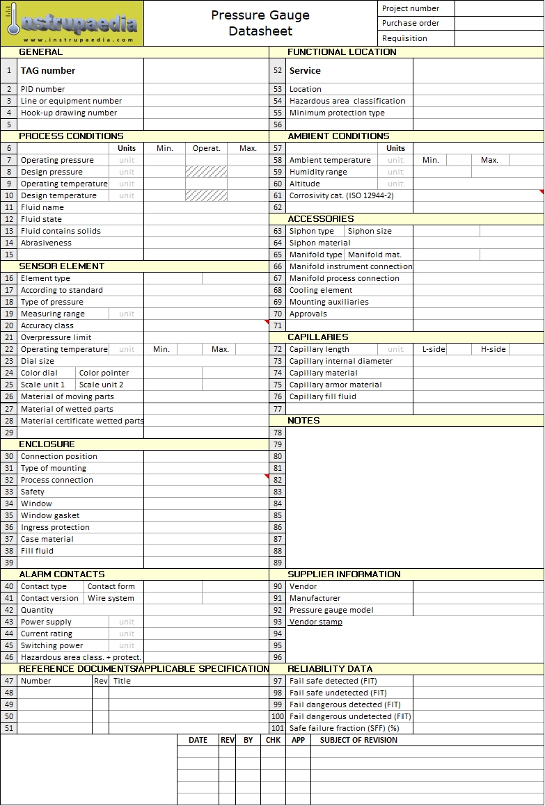
Pressure gauge datasheet
Specification sheet templates for Excel and pdf
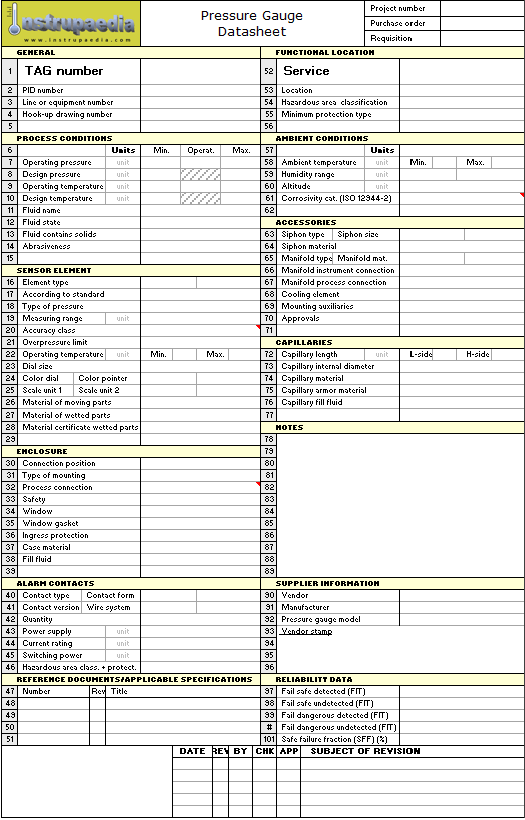
This datasheet template can specify pressure gauges with pressure-sensitive elements such as a Bourdon tube (C-type, helical or spiral), a diaphragm, a bellows, or a capsule.
Click once on the download button to download the datasheet in Excel format. If you prefer to first have a look at it in PDF, click the template image below. Further instructions for downloading and using this template are at the bottom of this page.
For those who are eager to learn more about pressure gauges, I recommend you visit one or more of the pages below where you will find information about the characteristics and properties of these pressure gauges:
Notice Instrupaedia has no link whatsoever with an existing manufacturer or supplier of this type of device, nor do we receive any commission on the use of this datasheet template. The only objective is to help you specify and order your material. You can fill in the datasheet template and send it to any supplier of pressure gauges you want.
The Excel file will be sent to your device after pressing the download button. If you do this from a computer or an Android phone, the file will end up in your download folder. From there you can open it by double-clicking on the file. Of course, you must have Microsoft Excel 2007 or later installed.
To perform a download to an iPhone or an iPad, tap on the download button of the desired datasheet. Then tap on the Share button and select the location where you want to save the file. This could be your Download folder, Dropbox or iCloud service. Now, tap the Save button and you’re done. To open the datasheet, you must first install a spreadsheet program on your device. In the app store, you can find programs like Numbers (Apple) or Microsoft Excel (Microsoft). Please note that these apps are not free. After the download, you can then open the file with your spreadsheet app.
The full functionality will not be available on a smartphone or a tablet. To be able to use all of the features of this datasheet, it is best to open it with Microsoft Excel 2007 or later via a laptop or desktop computer.
Instructions for using the template
Layout of the datasheet template
The template is divided into several blocks, with each block containing related information. For example, there is a block with information about the process conditions, another about the sensor element, or yet another about the enclosure …
Each block contains cells on the left with a description of a property on which a choice must be entered in the cells on the right.
Drop-down lists
For many of these cells, a choice can be made from a drop-down list. To do this, first click in the cell and then on the small triangle to the right of the cell. Make a choice from the list and select this choice by clicking on it. Your choice will be automatically entered in the selected cell. With the help of the drop-down lists, you can easily find the right technical term for the desired property.
Some cells do not have a drop-down list because the information that must be entered has endless possibilities. These cells have to be entered directly.
Error messages
The suggested choices from the drop-down lists correspond to what is available from most suppliers. If you think you need something else, you can enter the cell directly without making a choice from the list. However, some cells cannot be entered directly. This is to prevent you from entering something wrong. If you do it anyway, you will receive an error message with explanatory text. There are error messages that you can override and others that oblige you to make a choice from the drop-down list.
Comment blocks
Cells with a red triangle in the upper right corner open up a comment block when you hover over it. The comment relates to what you can enter in the cell or provides an explanation of the possible choices, so you will fully understand the impact of your choice.
Input messages
Every cell that has a drop-down list or a comment block also shows an input message when the cell is clicked. The input message appears in a rectangle below the cell and indicates whether you are obliged to choose from the list or whether you can enter something else. Sometimes the message also gives an extra tip.
Company logo
If you like you can put your own company name or logo in the bottom-left cell of the title block.
Although you can remove the Instrupaedia logo, please be so kind to leave it in so other people who receive this datasheet could also find it on the web and use it to their benefit too.
“Suggestions to improve this datasheet are always welcome.”
“If you think something needs to be changed, deleted or added, please leave a comment in the comments section below.”
Advertisement
Capsule pressure gauge
Pressure gauge working principle and properties
Capsule pressure gauge working principle
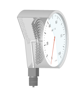
The sensing element of a capsule pressure gauge consists of two corrugated diaphragms welded together at their periphery to form a capsule.
The pressure to be measured is introduced into the capsule via an opening in the center of the first diaphragm. The center of the second diaphragm is connected to the transmission mechanism so that the deflection of the measuring element can be transmitted to the pointer.
When the pressure rises inside the capsule, both diaphragms will slightly deform. By making use of two diaphragms, the total deflection of the measuring element is twice as large.
In the pressure gauge animation below, the pressure is going in and out of the capsule, turning the pointer to the right and back to the left.
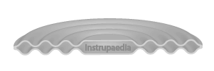
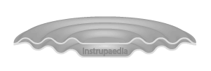
As you can see in the illustrations below, there are two types of capsules: convex and nested. A convex capsule is formed by attaching two convex diaphragms opposite to each other. A nested capsule consists of a convex and a concave diaphragm, also secured to one another along their periphery.
If the process pressure is applied along the exterior of the capsule, nested capsules have the advantage of being more resistant to overpressures.
Convex capsule
Nested capsule
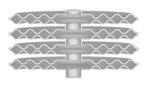
For the measurement of very small pressure differences, the deflection of a single capsule may be too small. Therefore, multiple capsules can be stacked on top of each other until sufficient displacement is obtained to move the pointer across the full scale. These stacks can be built with either convex or nested diaphragms.
Stacked capsules
Properties of the capsule gauge
With flat diaphragms, only very small deflections can be achieved since the elastic limit is reached quickly. Therefore, diaphragms are usually corrugated. These corrugations permit a larger deflection of the diaphragm before the elastic limit is reached.
A capsule having a diameter of 50mm (2 inches), consisting of two corrugated diaphragms which are welded to each other, can achieve a deflection of 1.5mm (0.06in).
The magnitude of the deflection depends also on the diameter of the diaphragm. The fact is that the deflection of a diaphragm is proportional to the fourth power of its diameter. Consequently, the deflection rapidly increases as the diameter of the diaphragm becomes larger. Doubling the diameter means that the deflection increases 16-fold.
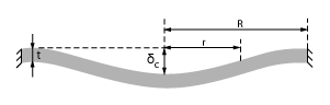
For flat, circular diaphragms which are clamped along their circumference, the deflection as a function of the radius can be calculated using the equation below.
This is a simplified formula that is only valid for small deflections of the diaphragm, in other words, where the ratio between the deflection of the diaphragm and the pressure applied to the diaphragm is linear. The term from the equation which represents the non-linear deflection has been neglected.
Where:
δ
=
deflection of the diaphragm
r
=
radial position
R
=
radius of the diaphragm
D
=
material stiffness of the diaphragm
P
=
pressure applied to the diaphragm
δc
=
centre deflection of the diaphragm
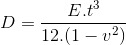
The material stiffness of the diaphragm (D) can be found using the following formula:
Where:
E
=
Young’s modulus of elasticity
t
=
thickness of the diaphragm
ν
=
Poisson’s ratio
For corrugated diaphragms, the equation will be a lot more complicated since it is necessary to take into account the number and the shape of the corrugations, as well as possibly a flat part in the middle of the diaphragm.
A corrugated zone ensures that the radial stress in the diaphragm is reduced by a factor of 1000 to 10000, allows for a reduction of the influence of temperature fluctuations by at least a factor of 120, and reduces the influence of welding stresses along the periphery of the diaphragm.
Because the capsule is made up of two diaphragms each having its own deflection, the sensitivity will be twice as large as that of the diaphragm pressure gauge. The sensitivity is also dependent on the diameter of the capsule. This can vary between 25mm (1 inch) and 150mm (6 inches). The larger the diameter, the greater the sensitivity.
The deflection of a diaphragm can transfer large forces. As a result, it becomes possible to drive a transmission mechanism with a large ratio. It is therefore perfectly possible, with the small deflection of a capsule, to move the pointer across the full scale. Even a small pressure acting on a diaphragm with a large diameter can generate sufficient force to drive the transmission mechanism.
Applications with capsules
Since the pressure chamber of a capsule is not self-draining, it cannot be used for liquids. Capsules are therefore only used for the measurement of gas pressures.
The ability to measure low pressures with diaphragms, along with the property of the double sensitivity of a capsule, ensures that capsules are the ideal sensors for use in a barometer.
In order to create more deflection and more sensitivity, capsules can be stacked on top of each other. A barometer will usually contain 2 to 5 capsules stacked on each other depending on the quality of the device.
Multiple capsules are required because the atmospheric pressure varies little, namely, only between 920 and 1050mbar. The small difference between the minimum and the maximum air pressure is sufficient for the stacked capsules to drive the pointer.
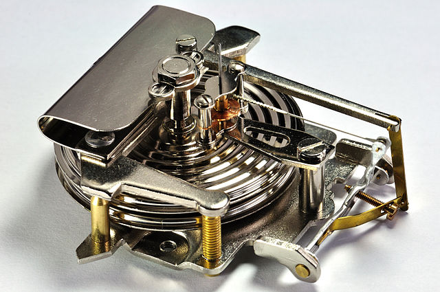
The picture below shows the inside of a barometer with two stacked capsules. Each capsule is evacuated and hermetically sealed. The air pressure acts on the outside of the capsules. To prevent the capsules from collapsing under increasing pressure, a spring is anchored on a bridge and attached to the top center of the capsule.
A barometer uses capsules. Photo by Gernek / CC BY-SA 3.0
Measuring range of capsule pressure gauges
Capsule pressure gauges are suitable for the measurement of very low negative and positive pressures ranging from 0 – 0.5 mbar to 0-1000 mbar with accuracy classes of 0.1 to 2.5. They can measure both relative and absolute as well as differential pressure.
Absolute pressure sensors
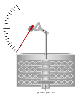
In absolute pressure sensors, the pressure chamber of the capsule is evacuated and hermetically sealed.
The capsule is mounted in a sealed housing. The process pressure is then introduced into the sealed housing through a process connection and applied to the exterior of the capsule.
Since the process pressure is compared to a nearly perfect vacuum inside the capsule, we will be measuring absolute pressure.
The link, which is fixed to the capsule, is passed through the wall of the housing towards the indicator by means of an almost frictionless bellows. The bellows ensure that the pressure in the housing will not leak along the link.
The capsules are designed to bottom on each other in case of overpressure in order to prevent damage.
Absolute pressure measurement with capsules.
Relative pressure sensors
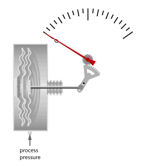
For the measurement of relative pressures, the process pressure is applied to the inside of the capsule. The capsule thus has a process connection in the middle of a diaphragm through which the process pressure is introduced.
The reference pressure, being the atmospheric pressure, is on the exterior of the capsule.
The measurement of relative pressure can be done with one or multiple capsules.
Relative pressure measurement with capsules.
Differential pressure sensors
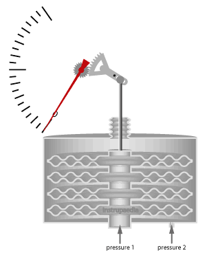
If the above relative pressure measurement is provided with a second connection and the enclosure at the height of the link is sealed with a bellows, two different pressures can be compared with each other. The resulting pressure, which is measured by the capsules, is the differential pressure of the two process pressures.
Differential pressure measurement with capsules.
Datasheet template
An easy configurable Excel template is available for specifying capsule pressure gauges. This pressure gauge datasheet is designed to define capsule pressure gauges for all kinds of applications.
Datasheet templates for other types of instruments can be found in the datasheet library.
Meaning of symbols on the dial of a pressure gauge
Some contain important information about the gauge
What can you learn about a pressure gauge by just looking at the dial? In addition to the measured pressure, there is still a lot of information you can read that is necessary for the use of the pressure gauge. This article covers all information and symbols which should be, mandatory or not, marked on the dial according to EN 837.
The unit of pressure
Bourdon tube
The bar is the preferred unit of pressure. If SI units are used, the indication will be displayed in kPa or MPa.
The marking is mandatory.
Diaphragm / Capsule
The bar is the preferred unit of pressure. The mbar is used for measuring ranges of 600 mbar or less. If SI-units are used, the indication will be in Pa, kPa or MPa.
The marking is mandatory.
The accuracy class
The accuracy class is always expressed as a percentage of the span and is associated with the nominal size of the manometer.
Bourdon tube
Defined classes: [0,1] – [0,25] – [0,6] – [1] – [1,6] – [2,5] – [4]
The marking is mandatory.
Relation: Nominal size – Accuracy class
Nominal size
Accuracy class
0,1
0,25
0,6
1
1,6
2,5
4
40 and 50
X
X
X
63
X
X
X
X
80
X
X
X
X
100
X
X
X
X
150 and 160
X
X
X
X
250
X
X
X
X
X
Diaphragm / Capsule
Defined classes: [0,6] – [1] – [1,6] – [2,5] – [4]
The marking is mandatory.
Relation: Nominal size – Accuracy class
Nominal size
Accuracy class
0,6
1
1,6
2,5
4
50
X
X
X
63
X
X
X
X
80
X
X
X
X
100
X
X
X
X
X
150 and 160
X
X
X
X
X
250
X
X
X
The type of pressure element
The kind of measuring element which is located inside the pressure gauge may be represented by a symbol on the dial.
Bourdon tube
The marking is not mandatory.
Type of Bourdon tube
Symbol
C-type
Spiral
Coiled
Diaphragm / Capsule
The marking is not mandatory.
Type of element
Symbol
Diaphragm
Capsule
Maximum steady working pressure
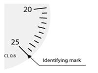
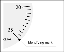
Pressure gauges that can operate continuously at the maximum scale value without compromising the accuracy after a period of time shall be provided with a symbol at the maximum scale value.
The marking is mandatory.
Maximum steady working pressure identification mark
The angle of inclination of the dial
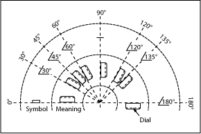
When the dial is not vertical but rotated at an angle relative to the horizontal plane, this shall be indicated on the dial. The manufacturer shall then calibrate the pressure gauge in that position.
The marking is mandatory.
Marking for the angle of inclination of the dial
The calibration temperature
For gauges with accuracy classes [0,1] – [0,25] and [0,6], the calibration temperature shall be indicated on the dial if it differs from the reference temperature. The reference temperature is 20°C.
The marking is mandatory but not for all accuracy classes.
The state of aggregation of the process medium
Bourdon tube
For gauges with accuracy classes [0,1] – [0,25] and [0,6] where the accuracy is only achieved for either gas (G) or liquid (F), this shall be marked on the dial. The use of the abbreviations G and F is not mandatory. The term “calibrated for gas” or the indication of the name of the process medium is also allowed.
The marking is mandatory but not for all accuracy classes.
Diaphragm / Capsule
The indication on the dial of the state of aggregation is not covered by the EN 837-3.
The marking is not mandatory.
The number of the followed standard
On the dial can be indicated whether the EN 837-1, if not the EN 837-3 is followed. When EN 837-1 is marked, you know instantly that it is a Bourdon tube. When the marking is EN 837-3, it can be a diaphragm or a capsule pressure gauge.
The marking is not mandatory.
The name of the manufacturer
To easily retrieve the manufacturer or supplier of the gauge, the name or logo of the manufacturer and/or supplier shall be marked.
The marking is mandatory.
The serial number of the device
Bourdon tube
For gauges with accuracy classes [0,1] and [0,25] the serial number must be marked. For the less accurate gauges, classes [0,6] to [4], this is not mandatory. When the pressure gauge is used for metrological purposes, the serial number is mandatory.
The marking is mandatory but not for all accuracy classes.
Diaphragm / Capsule
Pressure gauges used for metrological purposes shall have a serial number. For all other gauges this is not an obligation.
The marking is only mandatory for metrology.
The material of wetted parts
If the wetted parts are not made of brass, bronze, tin or hard solder, their material may be indicated on the dial.
The marking is not mandatory.
Safety pattern gauges
Bourdon tube
The marking S or together with the EN number, can be applied on the dial of safety pattern gauges, for:
Pressure gauges size 40 to 80, without baffle wall (type S2)
Pressure gauges size 40 to 250, with baffle wall (type S3)
The marking is mandatory but not for all sizes.
Diaphragm / Capsule
The indication of a safety pattern on the dial is not covered by the EN 837-3.
The marking is not mandatory.
Process medium: oxygen or acetylene
Bourdon tube
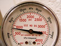
If the pressure gauge is used for measuring the pressure of oxygen or acetylene, respectively the word “oxygen” or “acetylene”, obligatory written in English, shall be marked. Since oil and grease can ignite spontaneously in contact with oxygen, also the symbol for “no lubrication” shall be marked.
Diaphragm / Capsule
The indication on the dial for oxygen or acetylene as a process medium is not covered by the EN 837-3.
The marking is not mandatory.
“Hey, your comments are valuable.”
“If there is anything you want to share with other people, please let it know in the comment section below.”
The majority of pressure gauges are designed according to an industry standard. This standard sets out the rules to which a product must comply. Topics such as overall dimensions, pressure ranges, accuracy classes, tolerances, testing,… and even packaging and marking are covered. The EN 837 is the European standard for pressure gauges and is divided into three parts:
Part 1:
Bourdon tube pressure gauges – Dimensions, metrology, requirements and testing.
Part 2:
Selection and installation – recommendations for pressure gauges.
Part 3:
Diaphragm and capsule pressure gauges – Dimensions, metrology, requirements and testing.
The safety design of a pressure gauge focuses primarily on Bourdon tube pressure gauges as this measuring principle is used for higher pressure ranges. The requirements imposed for the design of such gauges can be found in EN 837-1. The standard defines three types of safety designs to protect the operator from the failure of the Bourdon tube and the release of high-pressure gas into the casing of the pressure gauge. The released gas must be discharged to a safe area, away from the operator.
Blow-out device
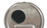
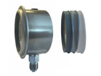
This is a part of the pressure gauge, usually a plug, located at the back or top of the case. When the pressure rises inside the casing, as a result of a failure of the Bourdon tube, the blow-out device (black plastic plug as shown in the picture below) will be blown away. The pressure inside the case must not become higher than half of the window-burst pressure.
The blow-out device must not be blocked by debris and dirt. When mounting the pressure gauge care should be taken to ensure that there is at least 20mm space left between the blow-out device and other objects in the vicinity of the pressure gauge.
When the pressure gauge is liquid-filled, a blow-out device is mandatory.
Blow-out device
Safety pattern pressure gauge
Safety pattern gauges ensure even higher protection for the operator in the event of a fatal rupture of the Bourdon tube. For this purpose they are using one or more of the following safety features:
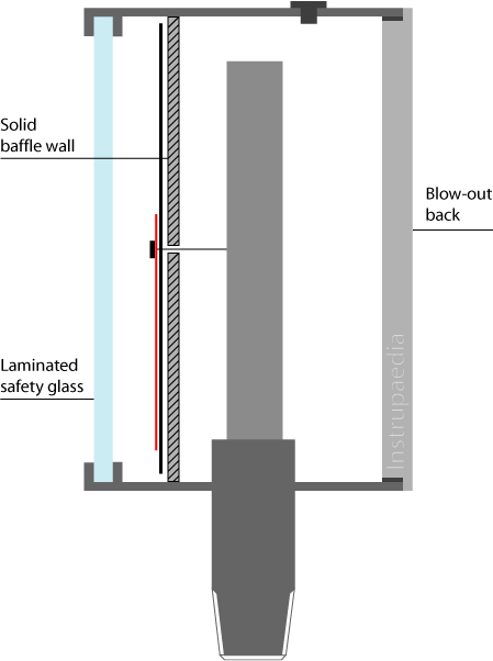
Laminated safety glass
A blow-out back
An internal baffle wall
There are two different kinds of safety pattern gauges: those with a baffle wall and those without.
Laminated safety glass
A laminated safety glass window is significantly stronger than a standard gauge glass window. It also will not splinter when it would collapse under the built-up pressure inside the casing. As an alternative to glass, non-splintering plastic may be used.
Blow-out back
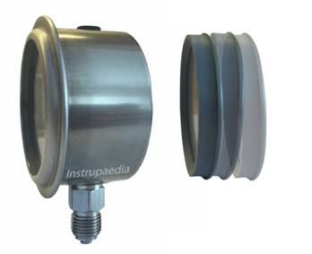
The largest possible surface, usually the entire back of the pressure gauge, is executed as a blow-out back. The blow-out back is blown away as a whole in the event of a fatal rupture of the Bourdon tube. There should be at least 20 mm of free space behind the pressure gauge in order not to obstruct the blow-out back.
The pressure inside the casing is allowed to rise to a maximum of half of the pressure that is needed to break the window with an absolute maximum of 1,5 bar (22 psi or 150 kPa).
The blow-out back is held in place with an O-ring so that the housing can be filled with liquid, if required.
Pressure gauge with blow-out back
A solid internal baffle wall
A baffle wall is a solid plate that is located between the Bourdon tube and the window. The plate sits right behind the dial and is welded to the inside of the case. Upon failure of the Bourdon tube, the baffle wall will protect the window from being pressurized and the built-up pressure will blow away the blow-out back towards a safe area.
The number and size of the holes in the baffle wall are to be reduced to a minimum. Holes are required for the pointer spindle, for fastening screws, or for liquid-filled gauges in order to allow the fill fluid to fill the space between the window and the baffle wall.
Full safety pattern gauge
Energy release test
Safety pattern gauges are subjected to an energy release test. This test simulates a fatal rupture of the Bourdon tube and the release of high-pressure gas into the casing of the pressure gauge.
S1 design
Pressure gauges built according to the S1 design just need to have a blow-out device.
S2 design
Safety pattern gauges having a diameter between 40 and 80 mm, without a baffle wall, are built according to the S2 design. These should successfully have passed the energy release test, have a window with laminated safety glass or non-splintering plastic, and have a blow-out device or a blow-out back.
S3 design
Safety pattern gauges having a diameter between 40 and 250 mm, with a baffle wall are built according to the S3 design. In addition to the requirements of the S2 design, they must be equipped with a blow-out back.
When do I need a safely designed pressure gauge?
Generally speaking, dry pressure gauges with a measuring range of 25 bar or less require no safety features while liquid-filled pressure gauges always need some safety features.
The EN 837-2 contains a more detailed classification where a distinction is made between liquid applications and gas or steam applications.
Measurement of liquid pressure
For dry pressure gauges, no safety features are required regardless of the gauge diameter or the measuring range.
For liquid-filled gauges, the S1 design should be used regardless of the gauge diameter or the measuring range.
Measurement of gas or steam pressure
For dry pressure gauges with a measuring range of 25 bar or less, no safety features are required for diameters less than 100 mm, and the S1 design should be used for diameters of 100 mm and above.
For dry pressure gauges with a measuring range above 25 bar, the S2 design should be used for diameters less than 100 mm, and the S3 design for diameters of 100 mm and above.
For liquid-filled pressure gauges with a measuring range of 25 bar or less, the S1 design should be used regardless of the diameter of the pressure gauge.
For liquid-filled pressure gauges with a measuring range above 25 bar, the S2 design should be used for diameters below 100 mm, and the S3 design should be used for diameters of 100 mm and above.
A few exceptions to the rule
Pressure gauges for applications on oxygen or acetylene shall always be of safety pattern type and thus make use of safety features according to the S2 or S3 design.
For applications on strong oxidizing agents, gauges shall not be filled with glycerin. Glycerin may react very violently when it comes into contact with certain strong oxidants. Below is a list of some of these substances:
Acetic anhydride
Aniline + nitrobenzene
Calcium hypochlorite
Chromium peroxide
Chromium trioxide
F2 + PbO
HClO4 + PbO
Potassium chlorate
Potassium permanganate
Potassium peroxide
Silver perchlorate
Sodium hydride
“Any questions or comments you may have are more than welcome.”
The discovery of resistance change as a result of strain
Lord Kelvin reported his findings in a paper describing the characteristics of copper and iron conductors subjected to mechanical strain. In an experiment, he had stretched copper and iron wires of the same length with a weight and claimed to have observed a change in electrical resistance when the wires were exposed to tensile strain.
It was only after his lecture to the Royal Society of London that he was informed about an experiment performed by Sir Charles Wheatstone in 1843. Wheatstone had done some testing with what he called “A Differential Resistance Measurer”, now known as the Wheatstone Bridge, and had discovered that slight differences in the length and even in the tensions of the wires were sufficient to disturb the equilibrium of his circuit.
1880
The discovery of the piezoelectric effect
The brothers Pierre and Jacques Curie found that certain types of crystals, such as quartz or tourmaline, can be electrically polarized when pressure was exerted along their hemihedral axes. They presented their findings to the Académie des Sciences in Paris but didn’t call it piezoelectricity yet (coming from the Greek “piezin”, which means to press).
Earlier scientists had already tried to find a relationship between pressure and polarization of these crystals but had failed.
A year after their initial discovery, they were doing the reverse experiment and found that a crystal deforms when it is exposed to an electric field.
1930
The unbonded wire strain gauge
Roy W. Carlson was a civil engineer who started his career as an inspector of concrete structures. He worked on the construction of dozens of dams in the United States. Compressive stress in the concrete is important in these structures but this could then not yet be measured and the authoritative opinion doubted the possibility of the development of such devices.
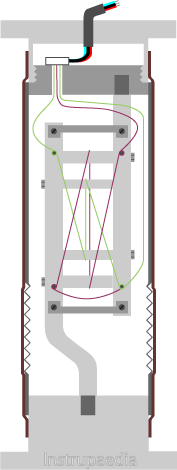
This thought challenged Carlson and he started research on a solution to measure compressive stress. He made use of an unbonded wire strain gauge (patent US2,036,458 A) to measure the strain inside a concrete structure. The strain gauge was incorporated into a sealed metal casing with flanges and covered with a rubber sleeve. The whole was then encapsulated in the concrete structure while it was poured.
Although the device worked well for the purpose it was designed for, there were also a few disadvantages, such as:
The device was large and heavy
The wires were fragile
The measurement was sensitive to vibration
As the wires were pretensioned, the device could work for extension as well as for compression strain, but too much compression would eliminate the pretension causing the wires to buckle and thereby making the device useless. Too much extension would cause the wires to elongate beyond their elastic limit with permanent deformation as a result.
A general problem arises with unbonded wire strain gauges when they have to be fixed at the place of measurement.
Unbonded wire strain gauges are mostly made of multiple resistive wires whereby half of them are stretched and the other half are contracted under the influence of the measured strain.
Telemetric device
1936
The carbon resistor strain gauge
Charles M. Kearns Jr. (Hamilton Standard Propeller Co) used a flattened carbon resistor bonded to an aluminum specimen (patent US2,252,464 A) and glued it on a blade of a propeller allowing him to measure the dynamic strains of the propeller which were the cause of many in-flight propeller breaks in the years 1931 to 1938. Based on his findings, he adapted the design of the propeller. The number of air crashes due to propeller failure fell from 40 to 0.
Although there were some advantages to the carbon resistor strain gauge, like the small size and weight or the simplicity of mounting it onto the test specimen, there were also a few drawbacks:
Poor accuracy
The wires were fragile
High creep effect causing changes in resistance over time.
Poor thermal stability
Inability to measure static strains
1938
The bonded wire strain gauge
Arthur C. Ruge (Massachusetts Institute of Technology) and Edward E. Simmons (California Institute of Technology) developed the bonded wire strain gauge (patent US2,393,714 A) almost simultaneously and independently from each other. Ruge started the patent application process but discovered that a year earlier Simmons had invented it already. Both men then have together applied for the patent.
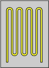
The design was still very simple: a fine wire with a high resistance has been zig-zag folded and glued to a piece of paper which in turn could be glued to the surface of the element of which one wishes to measure the strain. The number of folds in the pattern will influence the sensitivity of the strain gauge as the length of the wire exposed to strain will grow.
Bonded wire strain gauges had new advantages over unbonded wire strain gauges:
Improved measurement of compression strain because buckling of the wire is impossible due to the cementing of the wire to the test specimen.
Possibility to measure static strain
In 1939 Ruge founded a company to produce the SR-4 strain gauge. The S stands for Simmons, the R for Ruge and the 4 refers to four people (Simmons, Ruge, and their two assistants) who are responsible for this achievement. The SR-4 strain gauge was built up from four tungsten wires in the shape of a diamond.
The bonded wire strain gauge
1940
The piezoelectric pressure indicator
Hans Hintze and Hans Illgen (Zeiss Ikon AG) constructed a piezoelectric pressure indicator to measure the pressure within the pistons of combustion engines (patent US2,190,713 A).
Two quartz crystals are arranged in parallel between metal plates. The measured pressure acts on a metal membrane which transfers the pressure to the piezoelectric crystals. When the crystals are pressurized, they generate a small electric potential at both of their poles, which is picked up by the metal plates. The small current that arises accordingly will be amplified. The magnitude of the current corresponds exactly to that of the pressure.
1952
The foil strain gauge
Peter George Scott Jackson (Saunders-Roe Ltd) invented the foil strain gauges (patent GB720.325). Commissioned by the Saunders-Roe company he had to perform strain measurements on a new type of helicopter under development. He used the already existing wire strain gauges but encountered many problems with fatigue failure, slipring noise, and lack of sensitivity.
One day, on the way home, one of his engineers told him about the new photo etching technology which aimed to make amplifiers on a printed circuit board. Jackson immediately made the connection with his strain gauge problem.
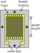
Using the photo etching technology a thin metallic resistance foil was etched on an electrically insulated and flexible backing made of lacquer, paper, or plastic. In order to be sufficiently flexible, the thickness of the backing was only 0,3 – 0,5 mm. The grid material consisted of 50% copper and 50% nickel, or an alloy of gold and silver.
Foil strain gauges had some advantages over bonded wire strain gauges:
Better heat dissipation because of the higher surface area. Therefore it can be used at a higher operating temperature range.
Better thermal stability
Simplified bonding technique
Less creep effect which is partly due to their better heat dissipation.
Better reproducibility because photo etching is a very precise technique that produces exactly the same gauges over and over again.
More flexible because the foil is very thin. So it better follows the surface of the test specimen.
Lower production cost
The foil strain gauge
1954
The capacitive pressure sensor
Carl P. Spaulding (Consolidated Engineering Corp.), an electrical engineer, came up with a capacitor pressure gauge (patent US2,667,786 A). With the previous art, it was not possible to measure very small pressures with sufficient accuracy because of the lack of sensitivity of the strain gauges. His intention was to build an instrument that could measure very small differential pressures in the order of magnitude 0,1 mm of Hg.
To achieve this accuracy, he had to create a perfect vacuum, stable to within 1 x 10⁻⁴ mm of Hg, and compare it to the measured pressure. His device made use of two conductive plates with a conductive membrane in the middle. The perfect vacuum was applied to one side of the membrane, while the measured pressure was along the other side of the membrane.
The device was able to measure differential pressures up to 0,5 mm of Hg with an accuracy of 0,1 %.
1954
The discovery of piezo-resistivity in semiconductors
C.S. Smith (Bell Laboratories) was the first to discover the piezoresistive properties of semiconducting silicon and germanium. In his seminal paper “Piezoresistance effect in germanium and silicon”, he wrote about the exceptionally large shear coefficients of both materials which couldn’t be explained in terms of previously known mechanisms.
1959
The first piezoresistive pressure sensor
Dr. A. D. Kurtz, a metallurgist, founded the company Kulite Semiconductor Products Inc. in 1959 and established, together with the company Bytrex Corporation, a jointly owned subsidiary called Kulite-Bytrex Corporation. Kulite-Bytrex was the first company to commercialize a pressure sensor based on the piezoresistive principle (licensed under the Bell patent US3,034,345 A), followed by the company Micro Systems one year later.
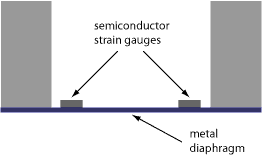
The resistance element was diffused into a substrate of silicon. The strain gauge was not provided with a backing causing the silicon substrate to be directly bonded to the metal diaphragm by means of epoxy.
Compared to the conventional metal wire and foil gauges the semiconductor strain gauge had an output almost 100 times larger.
Still using the adhesive bonding they were susceptible to creep and hysteresis.
Semiconductor strain gauges are nonlinear, sensitive to changes in temperature, and are more likely to drift compared to metal wire gauges. On the other hand, they have the benefit of higher resistivity and sensitivity and can be produced in sizes much smaller and cheaper than metal wire gauges.
Piezoresistive pressure sensor
1962
The diffused semiconductor strain gauge
Tufte (Honeywell Research) created the first diffused semiconductor strain gauge membrane after an idea of Pfann and Thurston in 1961.
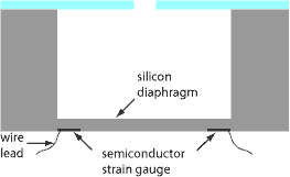
The diffused piezoresistive transducer uses a silicon diaphragm to transfer the strain onto the strain gauge. As the semiconductor strain gauge is integrated (diffused) into the silicon diaphragm epoxy bonding was no longer necessary. By avoiding the bonding, errors due to hysteresis and creep are excluded. The use of a silicone diaphragm instead of a metallic one also came with a few advantages.
A capacitive pressure transmitter with temperature compensation
William R. Polye (Bendix Corp.) worked out a temperature compensator for capacitive pressure transducers (patent US3,715,638 A).
The disadvantage of capacitive pressure transducers is their sensitivity to changes in temperature. On one hand, their dielectric constant can change, on the other hand, the distance between the plates may change due to the dilatation of the plates.
Polye designed an absolute pressure sensor with a body made of quartz and shaped like a doughnut. Inside the doughnut was a vacuum cavity that contained the two capacitor plates. On the outside of the body, two thin-film temperature sensors were deposited which he connected to a bridge circuit for temperature compensation. This made it possible to use the capacitive technique for low-pressure measurements with high accuracy.
1979
A capacitive pressure transducer with a ceramic body
Robert L. Bell (Kavlico Corp.) continued to build on the former design of capacitive transducers (patent US4,151,578 A).
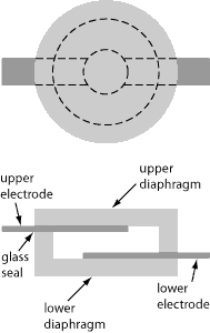
The quartz body is now replaced by a ceramic one. The transducer has an upper and a lower half which is bonded together by molded glass. The cavity between both halves is backfilled with a very small absolute pressure. This design is still used in today’s modern sensors.
Capacitive pressure transducer
References
Jyoti K. Sinha, Vibration Engineering and Technology of Machinery, Springer ISBN 978-3-319-09918-7 (eBook)
William N. Sharpe Jr. Prof., Handbook of Experimental Solid Mechanics, Springer ISBN 978-0-387-30877-7 (Online)
Béla G. Lipták, Instrument Engineers’ Handbook, Fourth Edition, Process Measurement and Analysis, ISA-The Instrumentation, Systems and Automation Society ISBN 0-8493-1083-0 (v. 1)
Gustav Gautschi, Piezoelectric Sensorics: Force Strain Pressure Acceleration and Acoustic Emission Sensors Materials and Amplifiers, Springer ISBN 678-3-662-04732-3 (eBook)







 together with the EN number, can be applied on the dial of