17 level measurement working principles
Continuous level measurement techniques
 10 November 2018
Level is one of the four most measured parameters in the industry.
Many different types of level measurement instruments are on the market. The right choice for your application is not easy and often depends on understanding the different level measurement techniques and knowing which process conditions are affecting the performance of the level sensor.
While most level sensing technologies are capable of functioning well at many different process conditions, there is no single level transmitter good for all applications.
But:
Once you understand the working principle of all these different technologies, your task will become a lot more simple.
And in today’s post, I will briefly describe the working principle of 17 different level measurement instruments.
At the bottom of the article, you will also find a table that shows which technology is suitable for specific process conditions.
1. Sight glass level gauge
A sight glass is the simplest device for measuring the liquid level in a vessel.
It is nothing more than a transparent glass tube, installed on the outside of a vessel, and connected to the bottom and the top of the vessel.
Sight glasses use the law of communicating vessels to indicate the level on the graduated gauge board.
The height of the liquid column in the sight glass will always be the same as the one inside the vessel.
Sometimes there are no graduations at all, and the sight glass is just showing the height of the liquid in the vessel.
2. Float level gauge
This old technique was the first attempt to automate the measurement of level in tanks after previously the level was measured manually by means of a rope with a float attached to it.
A float level gauge has a float hanging from a rope inside the tank. The rope is passed over two pulleys to a counterweight on the outside of the tank. The counterweight itself serves as an indicator on a direct reading gauge board.
Float level gauges operate on the principle of buoyancy, which means that a material with a lower density floats on a material with a higher density.
The float level indicator shown on the drawing is not the only existing type.
3. Displacer level transmitter principle
A displacer level transmitter is intended for liquid applications.
The displacer rod is immersed in the liquid and hanging on a spring or a torque tube. It always has a higher density than the liquid, so it doesn’t float.
When the vessel is completely filled and thus the displacer rod is fully immersed, there will still be a downward force on the spring.
The operation of a displacer level transmitter is based on Archimedes’ principle that states that the upward buoyant force that is exerted on a body immersed in a fluid, whether fully or partially submerged, is equal to the weight of the displaced fluid.
In this case, the buoyant force is acting on the displacer rod, pushing it upwards.
When the liquid level rises, the buoyant force will increase, reducing the apparent weight of the displacer rod. This reduces the length of the spring while the displacer moves upwards.
The up and down movement of the displacer rod is measured by sensors in the head of the transmitter and converted into an output signal.
4. Servo level transmitter principle
A small displacer hangs on a cable that is rolled up on a wire drum. The wire drum is magnetically coupled with a weight balance and is driven by a bi-directional servo motor.
When the displacer is lowered into the vessel and reaches the liquid surface, its apparent weight will decrease under the influence of the buoyant force.
The weight loss is detected by the weighing balance which then sends a signal to the control unit to stop the servo motor.
The length of the unwound cable is calculated by counting the number of revolutions of the wire drum by means of a set of Hall effect sensors and multiplying it by the known circumference of the drum.
Subtracting the result of this calculation from the total height of the vessel gives the height of the liquid in the tank.
When the level changes, the weighing balance will reposition the displacer until a new equilibrium is reached.
The servo level gauge is based on Archimedes’ principle as it uses the buoyant force during the measurement, and can therefore only be used for liquid level measurements.
5. Weight and cable level transmitter principle
The operation of electromechanical level transmitters, as they are sometimes called, is very similar to servo level transmitters.
The difference is mainly in the control of the probe and the internally used sensors.
Although the technique is used primarily for solids, also liquid levels can be measured by replacing the weight with a floating probe.
A weight is lowered through the roof of the tank until it reaches the surface of the product.
As soon as the probe touches the surface, the cable will become slack, and the unwinding of the cable will be stopped. The probe is then pulled back upwards.
The length of the unwound cable is measured both during the downward and upward movements, and the results are compared with each other. If there is a difference between the two measurement values, a new measurement starts.
The electronics convert the information about the measured length into an output signal that corresponds to the level or volume/weight in the tank.
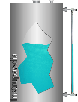
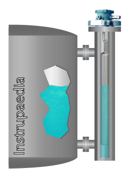
6. Magnetic level gauge principle

Magnetic level gauges are based on the law of magnetism.
Just like sight glasses, they are side-mounted to a tank and connected with valves to the bottom and top of the tank.
A magnetic level gauge consists of two main parts:
- A vertical pipe (also called ‘the chamber’), containing the process fluid and a float equipped with a magnet.
- A transparent enclosure mounted to the chamber with a number of indicators (flags) that are magnetically coupled to the float.
The float inside the chamber moves up and down with the surface of the liquid as it rises and falls.
Each time the float passes by a flag, their magnetic fields are coupled.
The magnetic coupling causes the flag to rotate around its axis, making the rear of the flag visible.
The liquid level becomes clearly indicated because the rear of the flag has a different color than the front.
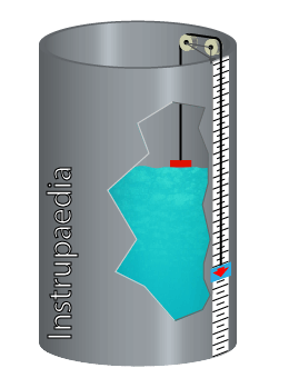
7. Resistive chain principle
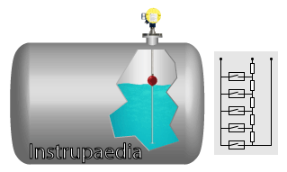
A resistive chain level sensor is based on the float principle and works in an almost similar way as a magnetic level gauge.
The sensor has a float, with an embedded permanent magnet, which slides along a vertical guide tube.
The tube has a built-in 3-wire potentiometer consisting of several individual resistors in series, each with its own reed contact.
When the float moves up and down, its magnetic field will close the reed contact located at the level of the float.
The closed reed contact thus becomes the tapping point on the potentiometer that divides its total resistance into 2 parts.
One part is used as the measured value, which is proportional to the level of the liquid and can be sent directly as a resistance value or converted to a current signal.
The finely stepped resistance chain makes the measurement virtually continuous.
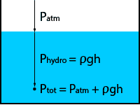
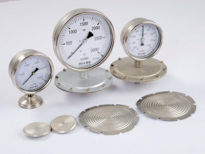
8. Hydrostatic level measurement principle
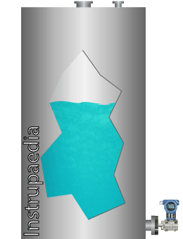
Hydrostatic level sensors are using the principle of hydrostatic pressure in a liquid column to measure the height of the level in a tank.
These sensors are actually pressure sensors that measure the hydrostatic pressure at a certain depth in the liquid, and then use the formula Phydro = ρgh to calculate the filling height (h) of the tank
As you can see from the formula, density (ρ) and gravity (g) are important factors in the determination of the level.
Any change in their value will have an influence on the accuracy of the measurement.
Hydrostatic level transmitters are used for level measurement in open or vented vessels where the gas phase on top of the liquid is at ambient pressure, and for sealed or gas-tight vessels where the pressure above the liquid is variable.
The sensors are equipped with a relative pressure measuring cell of which one side is exposed to the hydrostatic pressure and the other side is connected to:
- the ambient pressure, in the case of open vessels,
- the variable pressure on top of the liquid, in the case of sealed vessels.
In this way, the pressure acting on the liquid surface is automatically compensated.
9. Bubble tube principle
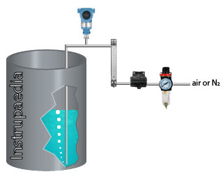
Bubbler tube level measurement is based on the hydrostatic pressure principle.
The bubbler is composed of:
- A dip tube
- A pressure transmitter
- A flow restrictor
- A source of compressed gas
The dip tube is inserted into the liquid and runs up to a few centimeters from the bottom of the tank.
Air or dry nitrogen is used as a source of compressed gas and connected to the other end of the tube.
The gas pressure is reduced by a flow restrictor, which could be a needle valve or a V-notch ball valve.
With the liquid level up to 100%, the gas flow can be adjusted so that only a small number of bubbles per minute flow out of the tube.
As the gas flows through the tube, the pressure inside the tube will rise until it equals the hydrostatic pressure of the liquid at the open end of the tube.
This hydrostatic pressure is measured by the pressure transmitter connected to the tube.
When the density of the liquid is known, the transmitter can now calculate the level using the formula Phydro = ρgh
10. Capacitive level sensor principle
The operation of a capacitance level transmitter is comparable to that of a variable capacitor.
The metal probe of the sensor serves as the one plate of the capacitor while the metal tank wall represents the other plate.
The liquid inside the tank acts as the dielectric material between the two plates.
When the liquid level rises, the capacity will increase. The value of this capacity is a measure for the height of the liquid in the tank.
If the liquid is non-conductive, the capacitor is formed between the metal probe and the metal tank wall.
If the liquid is conductive, the metal probe is insulated and the insulation serves as the dielectric material.
When the vessel is made of non-conductive material, the capacitive level sensor needs a reference probe that serves as the second plate of the capacitor.
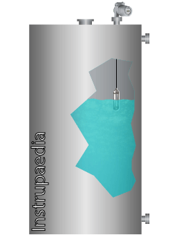
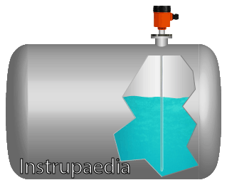
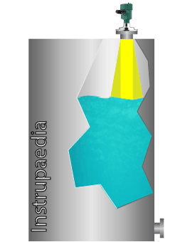
11. Ultrasonic level transmitter principle
The principle of an ultrasonic sensor is based on the time of flight (TOF) of an ultrasound pulse that moves back and forth between the sensor and the surface of the medium.
The sensor emits a high-frequency pulse in the range of 10 to 70 kHz, directed towards the surface of the medium.
When this pulse hits the surface, it bounces back to the sensor.
This reflected signal is also called ‘the echo’.
From the moment the echo arrives at the sensor, the transmitter calculates the distance to the surface using the formula:

With this information, the transmitter can now determine the level inside the vessel by subtracting the distance to the surface from the total height of the vessel.
An ultrasonic level transmitter is, in fact, nothing more than a high-tech timer with several features to be able to emit and receive ultrasound waves.
This technique can be used for both liquids and solids.
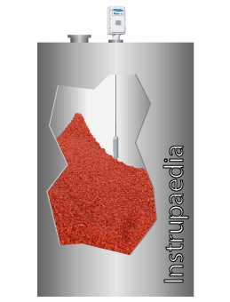
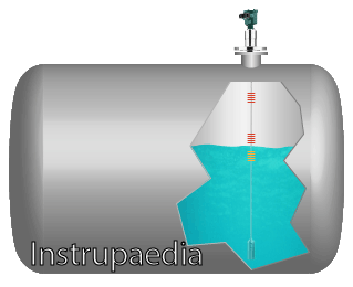
12. Magnetostrictive principle
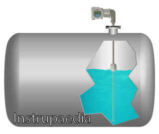
The principle that has been adopted for this measurement technique is called the Wiedemann effect.
This is one of the four effects that are related to magnetostriction, which is a property of ferromagnetic materials.
A magnetostrictive level sensor consists of a float that slides along a vertical ferromagnetic rod (also called the waveguide) during the rise and fall of the level. A permanent magnet is located inside the float at a precise location that corresponds to the level of the liquid.
If the exact position of this magnet could be measured, then the level of the liquid could be calculated.
So, how is this done:
At the start of the measurement, the transmitter sends a short current pulse down the waveguide and starts a timer from the moment the pulse leaves the transmitter.
As the current pulse is flowing through the waveguide, it creates a small circular magnetic field around the rod.
When the pulse arrives at the float, its circular magnetic field will intersect with the magnetic field of the permanent magnet.
The interaction between the two magnetic fields causes a mechanical torsional force in the waveguide as if the rod is locally twisted.
This torsional force is propagated along the waveguide as an acoustic torsional wave and flows back to the transmitter at a constant speed close to the speed of sound.
At the top of the waveguide, a pick-up coil or a piezo crystal will detect the torsional wave and convert it into a corresponding electrical signal.
At the same time, the timer is stopped and the time delay from the excitation of the waveguide to the reception of the corresponding acoustic wave is calculated.
From this time delay, knowing that the acoustic wave traveled at a constant speed, we can now calculate the position of the float.
The system for the time interval measurement is similar to the time of flight principle in ultrasonic level sensors.
13. Non-contact radar principle
Frequency modulated continuous wave (FMCW) and pulsed time-of-flight (ToF or PToF) are the two technologies used in modern radar-based level measurements.
Both of them are non-contact measurements, which means that the instrument is not touching the product inside the tank.
Pulsed time-of-flight is the oldest of both methods, which does not mean that it is less good than FMCW radar.
Pulsed radar systems use their antenna to emit a high-frequency electromagnetic wave (called ‘the pulse’) during a very short period of time.
The pulse travels with the speed of light directly towards the surface of the process medium and reflects from the medium surface due to a change in the dielectric constant.
The reflected pulse travels back to the transmitter which, on arrival, measures the time delay between the emitted and the received pulse.
It’s this time delay that is called ‘time of flight’.
The transmitter’s microprocessor then calculates the distance to the medium surface using the formula:

Since the height of the tank has already been programmed in the transmitter, the level can now be found by subtracting this distance from the tank height.
An FMCW radar works a little bit differently.
It differs in the way that the radar sends out and receives a continuous wave and instead of measuring the delay time, it measures the difference in frequency between the emitted and the received signal.
The radar’s oscillator transmits a linear frequency sweep at a fixed bandwidth and sweep time.
Simply said:
The emitted frequency runs up and down between two fixed values in a straight pattern like a triangle, during a fixed period of time.
When the electromagnetic wave hits the surface, it bounces back to the sensor.
The incoming reflection is received by the antenna and sent to a mixer to be compared with the signal that is being transmitted at that time.
The difference in frequency between the emitted and received signal is proportional to the time of flight, and to the distance to the medium surface.
Once the onboard microprocessor has calculated the distance to the surface, it becomes easy to find the level of the medium because the tank height is already programmed.
Non-contact radar level instruments may be equipped with various types of antennas and may operate at different frequencies.
14. Guided wave radar principle
Guided wave radar (GWR) is the latest invention, although already several years on the market, in radar level measurement technique and has its roots in the time domain reflectometry (TDR).
The TDR technology has been developed originally for detecting fractures in underground cables and more specifically for measuring the distance to the fracture.
GWR level transmitters are now using this method to measure the distance to the surface of the liquid (or solid, bulk product).
How it works:
The instrument’s antenna has the shape of a probe (the waveguide) and is immersed in the process medium. Its length determines the range of the measurement.
A high-frequency electromagnetic pulse is launched from the radar transmitter onto the waveguide towards the surface of the measured product.
The waves are staying close to the waveguide as they follow the probe towards the surface.
When the pulse hits the surface of the product, a significant part is reflected back up the probe while the other part penetrates the product.
The transmitter receives the reflected wave and calculates the time delay between the generated and reflected pulse.
The result of this calculation then serves to calculate the distance to the surface.
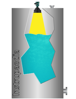
15. Laser level transmitter principle

Distance measurement using lasers is done with one of the following techniques:
- Pulsed lasers
- Frequency modulated continuous wave lasers
- Triangulation lasers
Although it is perfectly possible to measure level with all three techniques, only pulsed lasers are used for industrial applications.
This is because they are better suited to penetrate dust and steam.
Continuous-wave and triangulation lasers are more into short-range measurements, whereby continuous-wave lasers are used in highly accurate laboratory equipment and triangulation lasers are used in positioning applications and robotics.
So, since we are only talking about industrial laser level measurements, I will only explain the pulsed laser technology.
The principle of a pulsed laser level transmitter is again based on the time-of-flight technique.
The laser diode sends out a light pulse with a very sharp beam angle of less than 0,3°.
The reflection that comes off the surface of the process medium is captured by the receiver.
A very precise timing circuit measures the time delay between the transmitted and received pulse and sends the result to the microprocessor which calculates the distance to the surface using the formula:

Once this distance is known, the level can be found by making the difference between the height of the tank and the distance to the surface.
16. Load cell principle
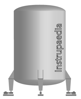
A load cell is a force transducer for measuring weight. Its output signal is proportional to the weight being measured.
Tanks and silos can be mounted on one or multiple load cells so that their entire weight can be measured.
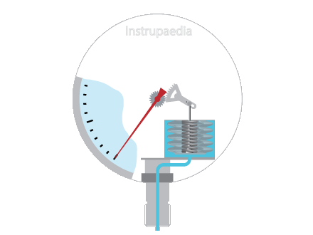
There are mainly three different technologies that can be categorized:
- Hydraulic
- Pneumatic
- Electronic
Hydraulic and pneumatic load cells use precision bourdon tubes or pressure transducers to give an indication of the weight while electronic load cells use various techniques to convert force into electrical signals.
The electronic load cell, more specifically the strain gauge load cell, is by far the most used type.
In order to determine the level, the weighing system must first be tared with an empty tank so that only the net content of the tank is measured.
The filling level is then determined by evaluating the measurement data.
The conversion to fill level can only take place if the density of the product is constant.
The calculation uses a strapping table in which weight and level are paired in steps.
When the measured weight is between two steps, the level is determined by interpolation.
17. Nuclear level measurement principle
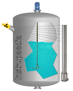
It may look a bit strange at first sight to use nuclear energy to measure something as simple as a product level in a vessel.
But sometimes there is no other choice.
How else would you measure the level of a product which enters the tank tangentially, with high velocity, creating a huge vortex inside the tank?
Usually, these kinds of applications have a vacuum on top of the fluid and are subject to vibrations.
Your options may be limited to just detecting the minimum and maximum level or measuring the level with a nuclear level transmitter.
In our example application, measuring this large vortex actually means determining an average level.
So, how can we measure the level with a nuclear source?
A nuclear level transmitter is composed of two main components:
- The radioactive source
- The radiation detector
Both components are mounted on the outside of the tank, right in front of each other on opposite sides of the tank.
The source is made of a radioactive substance, either cesium 137 or cobalt 60, and is constantly emitting gamma rays, straight through the vessel walls, in the direction of the radiation detector.
When the tank is empty, a lot of radiation will reach the detector. But when the level rises, the liquid or solid product will attenuate the radiation that reaches the detector.
Modern detectors use scintillation technology to convert the gamma radiation into a proportional amount of light which is then sensed by a photomultiplier and converted into an electrical signal.
Which technology solves your problem?
The table below lists a number of frequently occurring process conditions that may, to a greater or lesser extent, pose a problem to level measurement.
Depending on the operating principle on which the level measurement is based, this problem will be large, medium, or non-existent.
This table should give you a general idea of which technology to choose for your application.
| Good – This technology has little to no problem with this condition | |
| Moderate – Performance can be worse unless special measures are taken | |
| Poor – This condition is problematic or impossible to handle | |
| This technology is not suitable for level measurement of solids |

| Process conditions | Glass level gauges | Floats | Displacer | Servo | Cable & weight | Magnetic level gauges | Resistive chain | Hydrostatic | Air bubbler | Capacitance | Ultrasonic | Magnetostrictive | Non-contact radar pulse | Non-contact radar FMCW | Guided wave radar | Laser | Load cells | Nuclear (gamma) |
| Light foam | ||||||||||||||||||
| Dense foam | ||||||||||||||||||
| Surface turbulence | 4 | 2 | 2 | 2 | 2 | 2 | 2 | 2 | 2 | |||||||||
| Agitation | 2 | 2 | ||||||||||||||||
| Low vessel pressure (vacuum) | 7 | |||||||||||||||||
| High vessel pressure | 7 | 6 | ||||||||||||||||
| High process temperature | 6 | |||||||||||||||||
| Product density changes | 1 | 1 | 1 | 1 | 1 | 1 | 1 | 1 | 1 | 1 | ||||||||
| Product dielectric changes | 5 | 5 | 5 | |||||||||||||||
| Obstructions inside vessel | 4 | |||||||||||||||||
| Slurries | ||||||||||||||||||
| Viscous, sticky product | ||||||||||||||||||
| Product coating | 3 | |||||||||||||||||
| Corrosive product | ||||||||||||||||||
| Vapors | ||||||||||||||||||
| Solids | ||||||||||||||||||
| Dust | ||||||||||||||||||
| CIP (Cleaning In Place) | 6 |
- Only small density changes, otherwise too much accuracy loss
- Too much turbulence will result in unstable measurement
- Product coating on the vessel wall will influence the measurement result
- When installed in a stilling well
- Dielectric changes will influence the accuracy of interface measurement
- With glass window to isolate the transmitter from the process
- Use DP-cell when headspace is not at atmospheric pressure
Related topics

Leave a Comment
Your email address will not be published. Fields marked with * are required.