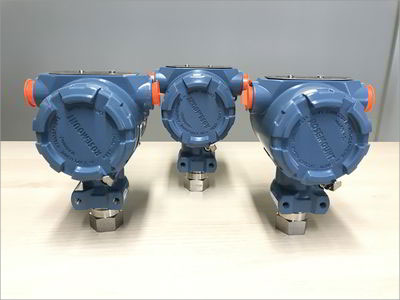
Potentiometric pressure transducer
A small pressure sensor with a lot of applications
 4 December 2017
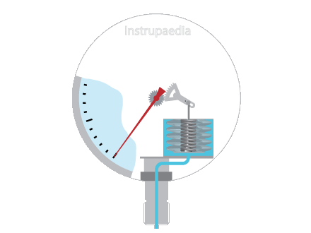
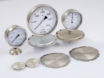
The use of pressure measurements dates back to the mid-19th century when the first mechanical pressure measurements were invented. The working principle was based on a balanced spring or a Bourdon tube, and the indication was represented by a pointer on a dial.
Only 80 years later, the first electric pressure transducers were invented. It started with a Bourdon tube attached to a potentiometer, creating the first potentiometric pressure transducer. A few years later followed by the unbonded and bonded strain gauges. The change in electrical resistance that is due to pressure changes, was always the basic principle. It took 30 more years before the principle of piezoresistivity was applied to pressure measurements.
Resistive transducers are widely used in the industry today because of their many advantages such as reliability, simple construction, mature design and production process, adjustable resolution, and maintenance-free properties.
Potentiometric transducer working principle
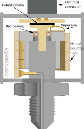
The principle of the potentiometric pressure measurement is based on the change in resistance of a potentiometer. The wiper of the potentiometer is mechanically connected to a pressure-sensitive element, such as a Bourdon tube, a bellows, a capsule, or a diaphragm. The deflection of the pressure-sensitive element determines the position of the wiper on the potentiometer. As a result, the resistance value changes between the wiper and one end of the potentiometer. This resistance value is a measure of the pressure applied to the sensing element.
Potentiometric sensor design
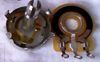
A potentiometer mainly consists of a resistance element having a connection terminal at each end, a sliding track that is connected to the third terminal, a wiper, and the housing.
The motion of the sensor is amplified through a mechanical transmission that moves the wiper over the full range of the potentiometer. By means of one or more sliding contacts, the wiper makes contact with the resistance path. Through a second (set) sliding contact(s), the tapped voltage is passed to the sliding track and made available at the output terminal of the potentiometer.
Due to friction between the sliding contacts and the resistance path, wear will occur on the potentiometer, which will change its resistance value and increase the noise. The wiper and the sliding contacts are usually made of a precious metal alloy (eg, a platinum alloy) to have a longer life and less noise.
The wiper has multiple sliding contacts to ensure that the potentiometer has a better resolution.
Depending on the application, the resistance element may be composed of resistance wire, a layer of carbon composite, a
The housing protects the potentiometer against dust and moisture. A pressure-resistant housing can be provided for use in potentially explosive atmospheres.
Both
At resistorguide.com you can find more detailed information about the operation and properties of the different types of potentiometers. Please note that not all potentiometers shown there can be used for potentiometric pressure transducers.
Rotary potentiometer
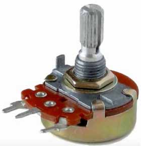
Photo by lainf / CC BY-SA 3.0
There are two design variations for a rotary potentiometer: single-turn and multi-turn. The most widely used industrial potentiometers are single-turn rotary potentiometers.
To move along the entire resistance range, single-turn potentiometers need to rotate less than 360°, while multi-turn potentiometers need to make multiple revolutions (e.g. 5, 10, 20, or 25 turns).
Due to their longer resistance path, multi-turn potentiometers have a higher resolution than single-turn potentiometers and are therefore much more accurate. The more complex design, however, also ensures that multi-turn potentiometers are more expensive.
Linear potentiometer
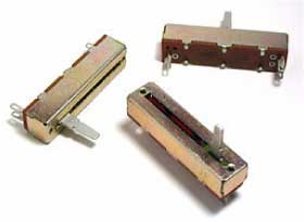
Photo by Omegatron / CC BY-SA 3.0
Unlike the rotary potentiometer, where the wiper performs a circular motion, the wiper of a linear potentiometer slides over a rectangular strip of resistance material in a straight line.
Because this potentiometer requires a large longitudinal opening for passage of the slider, there is a greater risk of dust and moisture getting caught between the sliding contacts and the resistance element. This causes more noise and even an interruption of the output signal.
Brushes or overlapping plastic foils covering that large opening can prevent dust from getting into the potentiometer but the risk is never excluded.
Wirewound potentiometer
A wirewound potentiometer is made by wrapping a resistance wire, usually nickel chrome, around a ceramic, plastic, or glass
Usually, nickel-chromium is used as the resistance wire because this material has a very low temperature coefficient of resistance, which leads to a more stable potentiometer. The coil is usually enclosed by a ceramic layer that only leaves the wiper’s path uncovered so that it can make contact with the resistance element.
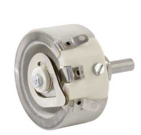
The wiper moves over the resistance element, sliding from one turn of wire to the next. Each time the wiper makes or breaks contact with a turn of wire, it causes an additional electrical signal called “noise”. The noise increases as the resistive element wears out.
Since the wiper does not follow the resistance wire but slides from one turn of wire to the next, the potentiometer resolution will also not be infinite. The tapped resistance value is each time incremented by the resistance of one turn of wire. The resolution is therefore determined by the resistance of one turn of wire and can be calculated as the reciprocal of the number of turns (1/n).
Due to the fact that the resistance wires are wrapped around a core, they also form a coil which creates an unwanted inductance. This results in poor frequency response when using frequencies from about 50 kHz.
|
|
||||||||||||
Carbon film potentiometer
A carbon film potentiometer consists of a thin layer of carbon composite ink,
In their
|
|
||||||||||
Cermet potentiometer
Cermet (CERamicMETal) potentiometers have a resistance element that consists of a mixture of metal particles and ceramics. Usually, the mixture contains less than 20% metal. The most commonly used metals are nickel, molybdenum, and cobalt.
Cermet resistive elements contain ceramic-based ink, which allows a higher level of heat absorption and dissipation than most other composite materials used in potentiometers. They also have a wider temperature range compared to other composites, partly because they have a
|
|
||||||||||||||||
Plastic film potentiometer
The plastic film is sometimes also referred to as conductive plastic. The resistance element is composed of a
The temperature coefficient of conductive plastic can vary widely depending on the production process used. Sometimes metal powders such as nickel, silver, or copper are added to the mixture to improve the temperature coefficient. The material selection of the substrate also influences the temperature coefficient. A plastic substrate provides better results because of better compatibility with the plastic film resistance element.
|
|
||||||||||||||
The potentiometer as a voltage divider
In principle, a potentiometer is nothing more than a voltage divider. The wiper divides the resistance element into two variable resistors whose resistance value depends on the position of the wiper. The voltage Vs connected to the resistance element is divided between the two variable resistors R1 and R2.

The voltage across the load RL can then be calculated as follows:
If we assume that RL is very large, relative to R1 and R2, we can divide the numerator and denominator by RL. We then get the following simplified formula:
Pros and cons of potentiometric transducers
One of the biggest benefits is the simplicity of the technology. A problem with a potentiometer can often be solved with an ordinary multimeter.
They can also be easily adapted to the application because they can be manufactured very small and can, therefore, be installed in very small spaces.
Due to the high output signal level, there is no need for signal enhancement and no need for conditioning of the signal. Therefore, they can be used for low power applications, because 0.1 mA from the transmitter is sufficient to read the resistance value. In addition, they are quite cheap because the resistance value can easily be converted to a standard voltage or current signal.
Their disadvantages include the large hysteresis that results from the wiper’s sliding friction over the resistance element, the vibration sensitivity which can be largely solved by the use of multi-finger wipers, and their short life which is mainly due to the friction of the wiper on the resistance element.
|
|
||||||||||||||||||
Selection criteria for potentiometric transducers
Making a good choice for a potentiometric transducer is not an easy task. Technicians in charge of this task will benefit from a good knowledge of existing technologies and the process parameters of the application. Besides the cost of the device, the following technical aspects are best considered:
- The expected accuracy and linearity
- The required range
- The repeatability
- The resolution
- The required torque/force to move the wiper
- Environmental factors like vibration, dust, temperature, humidity
- The expected life span
- The stroke/deflection of the sensor
- The speed of movement
Applications with potentiometric transducers
Potentiometric pressure transducers can be used to measure absolute, relative, or differential pressure depending on how the pressure sensor is built.
They are used for industrial and military purposes as oil pressure gauges for display on the dashboard, flow measurement of air supply to combustion engines, or pressure measurements for ground support equipment at airports.
In addition to pressure measurement applications, the potentiometric transducer is also used for many other applications such as positioning, displacement, level, flow rate measurement, etc.
Actuators use potentiometers for simple position feedback or
Other applications for potentiometric transducers:
- Suspension travel
- Wing deflection
- Medical equipment
- Steering position
- Scissor lift
- Cut-off saw
- Position of the fork in forklift trucks
- Brake position
- Clutch position
- Throttle position
Datasheet template
An easy configurable Excel template is available for specifying pressure transmitters. This datasheet is designed to define pressure transmitters for all kinds of applications.
Datasheet templates for other types of instruments can be found in the datasheet library.
References
- Regtien Paul P.L. 2012. Sensors for Mechatronics. Elsevier. 322pp
- Singh S.K. 2007. Industrial Instrumentation & Control, 2e. Tata McGraw-Hill Publishing Company Limited. 697pp
- Lipták Béla G. 2003. Instrument Engineers’ Handbook, Vol. 1: Process Measurement and Analysis, 4th Edition. CRC Press. 1867pp
- Du Winncy Y. 2015. Resistive, Capacitive, Inductive and Magnetic Sensor Technologies. CRC Press. 408pp
- Du Winncy Y. and Yelich Scott W. 2012. Resistive and Capacitive Based Sensing Technologies. In: Yurish Sergey Y. (ed). Modern Sensors, Transducers and Sensor Networks. International Frequency Sensor Association Publishing. 422pp
- Todd C.D., Hardison W.T. and Galvan W.E. (eds). 1975-2008. The Potentiometer Handbook, Users’ Guide to Cost-effective Applications. McGraw-Hill Book Company. 227pp
- Wikipedia(NL). 2017. Potentiometer.
- Wikipedia(EN). 2017. Potentiometer.
- Wikipedia(EN). 2017. Resistor.
- Resistorguide. Potentiometer.
- Conrad. Weerstanden.
- John. 2011. Linear Potentiometer Transducer.
Related topics

Leave a Comment
Your email address will not be published. Fields marked with * are required.