History of electronic pressure transducers
Inventions that changed the world
 24 January 2016
1856

The discovery of resistance change as a result of strain
Lord Kelvin reported his findings in a paper describing the characteristics of copper and iron conductors subjected to mechanical strain. In an experiment, he had stretched copper and iron wires of the same length with
It was only after his lecture to the Royal Society of London that he was
1880
The discovery of the piezoelectric effect
The brothers Pierre and Jacques Curie found that certain types of crystals, such as quartz or tourmaline, can be electrically polarized when pressure was exerted along their hemihedral axes. They presented their findings to the Académie des Sciences in Paris but didn’t call it piezoelectricity yet (coming from the Greek “piezin”, which means to press).
Earlier scientists had already tried to find a relationship between pressure and polarization of these crystals but had failed.
A year after their initial discovery, they were doing the reverse experiment and found that a crystal deforms when it is exposed to an electric field.
1930
The unbonded wire strain gauge
Roy W. Carlson was a civil engineer who started his career as an inspector of concrete structures. He worked on the construction of dozens of dams in the United States. Compressive stress in the concrete is important in these structures but this could then not yet be measured and the authoritative opinion doubted the possibility of the development of such devices.
This thought challenged Carlson and he started research on a solution to measure compressive stress. He made use of an unbonded wire strain gauge (patent US2,036,458 A) to measure the strain inside a concrete structure. The strain gauge was incorporated into a sealed metal casing with flanges and covered with a rubber sleeve. The whole was then encapsulated in the concrete structure while it was poured.
Although the device worked well for the purpose it was designed for, there were also a few disadvantages, such as:
- The device was large and heavy
- The wires were fragile
- The measurement was sensitive to vibration
- As the wires were pretensioned, the device could work for extension as well as for compression strain, but too much compression would eliminate the pretension causing the wires to buckle and thereby making the device useless. Too much extension would cause the wires to elongate beyond their elastic limit with permanent deformation as a result.
- A general problem arises with unbonded wire strain gauges when they have to be fixed at the place of measurement.
Unbonded wire strain gauges are mostly made of multiple resistive wires whereby half of them are stretched and the other half are contracted under the influence of the measured strain.
1936
The carbon resistor strain gauge
Charles M. Kearns Jr. (Hamilton Standard Propeller Co) used a flattened carbon resistor bonded to an aluminum specimen (patent US2,252,464 A) and glued it on a blade of a propeller allowing him to measure the dynamic strains of the propeller which were the cause of many in-flight propeller breaks in the years 1931 to 1938. Based on his findings, he adapted the design of the propeller. The number of air crashes due to propeller failure fell from 40 to 0.
Although there were some advantages to the carbon resistor strain gauge, like the small size and weight or the simplicity of mounting it onto the test specimen, there were also a few drawbacks:
- Poor accuracy
- The wires were fragile
- High creep effect causing changes in resistance over time.
- Poor thermal stability
- Inability to measure static strains
1938
The bonded wire strain gauge
Arthur C. Ruge (Massachusetts Institute of Technology) and Edward E. Simmons (California Institute of Technology) developed the bonded wire strain gauge (patent US2,393,714 A) almost simultaneously and independently from each other. Ruge started the patent application process but discovered that a year earlier Simmons had invented it already. Both men then have together applied for the patent.
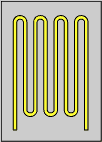
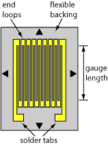
The design was still very simple: a fine wire with a high resistance has been zig-zag folded and glued to a piece of paper which in turn could be glued to the surface of the element of which one wishes to measure the strain. The number of folds in the pattern will influence the sensitivity of the strain gauge as the length of the wire exposed to strain will grow.
Bonded wire strain gauges had new advantages over unbonded wire strain gauges:
- Improved measurement of compression strain because buckling of the wire is impossible due to the cementing of the wire to the test specimen.
- Possibility to measure static strain
In 1939 Ruge founded a company to produce the SR-4 strain gauge. The S stands for Simmons, the R for Ruge and the 4 refers to four people (Simmons, Ruge, and their two assistants) who are responsible for this achievement. The SR-4 strain gauge was built up from four tungsten wires in the shape of a diamond.
1940
The piezoelectric pressure indicator
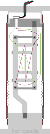
Hans Hintze and Hans Illgen (Zeiss Ikon AG) constructed a piezoelectric pressure indicator to measure the pressure within the pistons of combustion engines (patent US2,190,713 A).
Two quartz crystals are arranged in parallel between metal plates. The measured pressure acts on a metal membrane which transfers the pressure to the piezoelectric crystals. When the crystals are pressurized, they generate a small electric potential at both of their poles, which is picked up by the metal plates. The small current that arises accordingly will be amplified. The magnitude of the current corresponds exactly to that of the pressure.
1952
The foil strain gauge
Peter George Scott Jackson (Saunders-Roe Ltd) invented the foil strain gauges (patent GB720.325). Commissioned by the Saunders-Roe company he had to perform strain measurements on a new type of helicopter under development. He used the already existing wire strain gauges but encountered many problems with fatigue failure, slipring noise, and lack of sensitivity.
One day, on the way home, one of his engineers told him about the new photo etching technology which aimed to make amplifiers on a printed circuit board. Jackson immediately made the connection with his strain gauge problem.
Using the photo etching technology a thin metallic resistance foil was etched on an electrically insulated and flexible backing made of lacquer, paper, or plastic. In order to be sufficiently flexible, the thickness of the backing was only 0,3 – 0,5 mm. The grid material consisted of 50% copper and 50% nickel, or an alloy of gold and silver.
Foil strain gauges had some advantages over bonded wire strain gauges:
- Better heat dissipation because of the higher surface area. Therefore it can be used at a higher operating temperature range.
- Better thermal stability
- Simplified bonding technique
- Less creep effect which is partly due to their better heat dissipation.
- Better reproducibility because photo etching is a very precise technique that produces exactly the same gauges over and over again.
- More flexible because the foil is very thin. So it better follows the surface of the test specimen.
- Lower production cost
1954
The capacitive pressure sensor
Carl P. Spaulding (Consolidated Engineering Corp.), an electrical engineer, came up with a capacitor pressure gauge (patent US2,667,786 A). With the previous art, it was not possible to measure very small pressures with sufficient accuracy because of the lack of sensitivity of the strain gauges. His intention was to build an instrument that could measure very small differential pressures in the order of magnitude 0,1 mm of Hg.
To achieve this accuracy, he had to create a perfect vacuum, stable to within 1 x 10⁻⁴ mm of Hg, and compare it to the measured pressure. His device made use of two conductive plates with a conductive membrane in the middle. The perfect vacuum was applied to one side of the membrane, while the measured pressure was along the other side of the membrane.
The device was able to measure differential pressures up to 0,5 mm of Hg with an accuracy of 0,1 %.
1954
The discovery of piezo-resistivity in semiconductors
C.S. Smith (Bell Laboratories) was the first to discover the piezoresistive properties of semiconducting silicon and germanium. In his seminal paper “Piezoresistance effect in germanium and silicon”, he wrote about the exceptionally large shear coefficients of both materials which couldn’t be explained in terms of previously known mechanisms.
1959
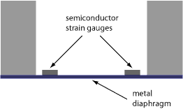
The first piezoresistive pressure sensor
Dr. A. D. Kurtz, a metallurgist, founded the company Kulite Semiconductor Products Inc. in 1959 and established, together with the company Bytrex Corporation, a jointly owned subsidiary called Kulite-Bytrex Corporation. Kulite-Bytrex was the first company to commercialize a pressure sensor based on the piezoresistive principle (licensed under the Bell patent US3,034,345 A), followed by the company Micro Systems one year later.
The resistance element was diffused into a substrate of silicon. The strain gauge was not provided with a backing causing the silicon substrate to be directly bonded to the metal diaphragm by means of epoxy.
Compared to the conventional metal wire and foil gauges the semiconductor strain gauge had an output almost 100 times larger.
Still using the adhesive bonding they were susceptible to creep and hysteresis.
Semiconductor strain gauges are nonlinear, sensitive to changes in temperature, and are more likely to drift compared to metal wire gauges. On the other hand, they have the benefit of higher resistivity and sensitivity and can be produced in sizes much smaller and cheaper than metal wire gauges.
1962
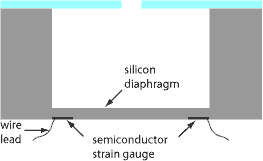
The diffused semiconductor strain gauge
Tufte (Honeywell Research) created the first diffused semiconductor strain gauge membrane after an idea of Pfann and Thurston in 1961.
The diffused piezoresistive transducer uses a silicon diaphragm to transfer the strain onto the strain gauge. As the semiconductor strain gauge is integrated (diffused) into the silicon diaphragm epoxy bonding was no longer necessary. By avoiding the bonding, errors due to hysteresis and creep are excluded. The use of a silicone diaphragm instead of a metallic one also came with a few advantages.
Photolithographic techniques are used to create these piezo-resistors.
Semiconductor strain gauges have a number of advantages over bonded wire or foil strain gauges:
- Higher sensitivity (gauge factor is 50 to nearly 100 times higher)
- Smaller sizes
- Higher resistance
- Hysteresis and creep due to adhesives are excluded
- Lower non-linearity
- Higher fatigue life
- Increased ambient temperature range
1973
A capacitive pressure transmitter with temperature compensation
William R. Polye (Bendix Corp.) worked out a temperature compensator for capacitive pressure transducers (patent US3,715,638 A).
The disadvantage of capacitive pressure transducers is their sensitivity to changes in temperature. On one hand, their dielectric constant can change, on the other hand, the distance between the plates may change due to the dilatation of the plates.
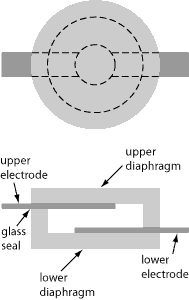
Polye designed an absolute pressure sensor with a body made of quartz and shaped like a doughnut. Inside the doughnut was a vacuum cavity that contained the two capacitor plates. On the outside of the body, two thin-film temperature sensors were deposited which he connected to a bridge circuit for temperature compensation. This made it possible to use the capacitive technique for low-pressure measurements with high accuracy.
1979
A capacitive pressure transducer with a ceramic body
Robert L. Bell (Kavlico Corp.) continued to build on the former design of capacitive transducers (patent US4,151,578 A).
The quartz body is now replaced by a ceramic one. The transducer has an upper and a lower half which is bonded together by molded glass. The cavity between both halves is backfilled with a very small absolute pressure. This design is still used in today’s modern sensors.
References
- Jyoti K. Sinha, Vibration Engineering and Technology of Machinery, Springer ISBN 978-3-319-09918-7 (eBook)
- William N. Sharpe Jr. Prof., Handbook of Experimental Solid Mechanics, Springer ISBN 978-0-387-30877-7 (Online)
- Béla G. Lipták, Instrument Engineers’ Handbook, Fourth Edition, Process Measurement and Analysis, ISA-The Instrumentation, Systems and Automation Society ISBN 0-8493-1083-0 (v. 1)
- Kulite. Strain Gage Manual.
- Gustav Gautschi, Piezoelectric Sensorics: Force Strain Pressure Acceleration and Acoustic Emission Sensors Materials and Amplifiers, Springer ISBN 678-3-662-04732-3 (eBook)
- APS. 2014. March 1880: The Curie Brothers Discover Piezoelectricity.
Related topics
Leave a Comment
Your email address will not be published. Fields marked with * are required.