Safely designed pressure gauges
Pressure gauge design for safe operation
 28 July 2016
European standard EN 837
The majority of pressure gauges are designed according to an industry standard. This standard sets out the rules to which a product must comply. Topics such as overall dimensions, pressure ranges, accuracy classes, tolerances, testing,… and even packaging and marking are covered. The EN 837 is the European standard for pressure gauges and is divided into three parts:
| Part 1: | Bourdon tube pressure gauges – Dimensions, metrology, requirements and testing. |
| Part 2: | Selection and installation – recommendations for pressure gauges. |
| Part 3: | Diaphragm and capsule pressure gauges – Dimensions, metrology, requirements and testing. |
The safety design of a pressure gauge focuses primarily on Bourdon tube pressure gauges as this measuring principle is used for higher pressure ranges. The requirements imposed for the design of such gauges can be found in EN 837-1. The standard defines three types of safety designs to protect the operator from the failure of the Bourdon tube and the release of high-pressure gas into the casing of the pressure gauge. The released gas must be discharged to a safe area, away from the operator.

Blow-out device
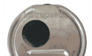
This is a part of the pressure gauge, usually a plug, located at the back or top of the case. When the pressure rises inside the casing, as a result of a failure of the Bourdon tube, the blow-out device (black plastic plug as shown in the picture below) will be blown away. The pressure inside the case must not become higher than half of the window-burst pressure.
The blow-out device must not be blocked by debris and dirt. When mounting the pressure gauge care should be taken to ensure that there is at least 20mm space left between the blow-out device and other objects in the vicinity of the pressure gauge.
When the pressure gauge is liquid-filled, a blow-out device is mandatory.
Safety pattern pressure gauge
Safety pattern gauges ensure
- Laminated safety glass
- A blow-out back
- An internal baffle wall
There are two different kinds of safety pattern gauges: those with a baffle wall and those without.
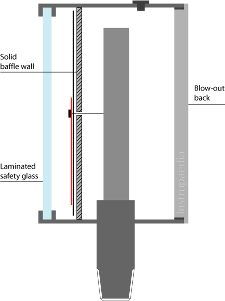
Laminated safety glass
A laminated safety glass window is significantly stronger than a standard gauge glass window. It also will not splinter when it would collapse under the built-up pressure inside the casing. As an alternative to glass, non-splintering plastic may be used.
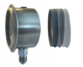
Blow-out back
The largest possible surface, usually the entire back of the pressure gauge, is executed as a blow-out back. The blow-out back is blown away as a whole in the event of a fatal rupture of the Bourdon tube. There should be at least 20 mm of free space behind the pressure gauge in order not to obstruct the blow-out back.
The pressure inside the casing is allowed to rise to a maximum of half of the pressure that is needed to break the window with an absolute maximum of 1,5 bar (22 psi or 150 kPa).
The blow-out back is held in place with an O-ring so that the housing can be filled with liquid, if required.
A solid internal baffle wall
A baffle wall is a solid plate that is located between the Bourdon tube and the window. The plate sits right behind the dial and is welded to the inside of the case. Upon failure of the Bourdon tube, the baffle wall will protect the window from being pressurized and the built-up pressure will blow away the blow-out back towards a safe area.
The number and size of the holes in the baffle wall are to be reduced to a minimum. Holes are required for the pointer spindle, for fastening screws, or for liquid-filled gauges in order to allow the fill fluid to fill the space between the window and the baffle wall.
Energy release test
Safety pattern gauges are subjected to an energy release test. This test simulates a fatal rupture of the Bourdon tube and the release of high-pressure gas into the casing of the pressure gauge.
S1 design
Pressure gauges built according to the S1 design just need to have a blow-out device.
S2 design
Safety pattern gauges having a diameter between 40 and 80 mm, without a baffle wall, are built according to the S2 design. These should successfully have passed the energy release test, have a window with laminated safety glass or non-splintering plastic, and have a blow-out device or a blow-out back.
S3 design
Safety pattern gauges having a diameter between 40 and 250 mm, with a baffle wall are built according to the S3 design. In addition to the requirements of the S2 design, they must be equipped with a blow-out back.
When do I need a safely designed pressure gauge?
Generally speaking, dry pressure gauges with a measuring range of 25 bar or less require no safety features while liquid-filled pressure gauges always need some safety features.
The EN 837-2 contains a more detailed classification where a distinction is made between liquid applications and gas or steam applications.
Measurement of liquid pressure
For dry pressure gauges, no safety features are required regardless of the gauge diameter or the measuring range.
For liquid-filled gauges, the S1 design should be used regardless of the gauge diameter or the measuring range.
Measurement of gas or steam pressure
For dry pressure gauges with a measuring range of 25 bar or less, no safety features are required for diameters less than 100 mm, and the S1 design should be used for diameters of 100 mm and above.
For dry pressure gauges with a measuring range above 25 bar, the S2 design should be used for diameters less than 100 mm, and the S3 design for diameters of 100 mm and above.
For liquid-filled pressure gauges with a measuring range of 25 bar or less, the S1 design should be used regardless of the diameter of the pressure gauge.
For liquid-filled pressure gauges with a measuring range above 25 bar, the S2 design should be used for diameters below 100 mm, and the S3 design should be used for diameters of 100 mm and above.
A few exceptions to the rule
Pressure gauges for applications on oxygen or acetylene shall always be of safety pattern type and thus make use of safety features according to the S2 or S3 design.
For applications on strong oxidizing agents, gauges shall not be filled with glycerin. Glycerin may react very violently when it comes into contact with certain strong oxidants. Below is a list of some of these substances:
- Acetic anhydride
- Aniline + nitrobenzene
- Calcium hypochlorite
- Chromium peroxide
- Chromium trioxide
- F2 + PbO
- HClO4 + PbO
- Potassium chlorate
- Potassium permanganate
- Potassium peroxide
- Silver perchlorate
- Sodium hydride
“Any questions or comments you may have are more than welcome.”
Related topics

Leave a Comment
Your email address will not be published. Fields marked with * are required.