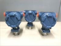
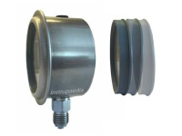
Diaphragm pressure gauge
Pressure gauge working principle and properties
 5 June 2022
Diaphragm pressure gauge working principle
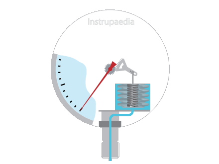
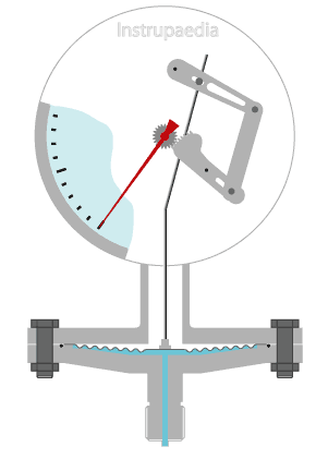
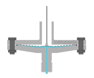
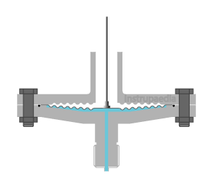
The diaphragm pressure gauge consists of a circular membrane, made from sheet metal of precise dimensions, which can either be flat or corrugated.
The diaphragm is mechanically connected to the transmission mechanism which will amplify the small deflections of the diaphragm and transfer them to the pointer
“Check out other pressure gauge animations:”
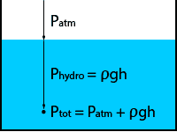
The process pressure is applied to the lower side of the diaphragm, while the upper side is at atmospheric pressure. The differential pressure arising across the diaphragm lifts the diaphragm and puts the pointer in motion.
The deflection of the diaphragm is very small (+/- 1 mm) making it necessary to use a high-ratio multiplying movement to rotate the pointer along the full length of the scale. The actuation of such a high-ratio transmission mechanism is possible because diaphragm deflection can generate large forces.
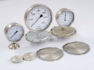
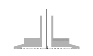
Flat and corrugated diaphragms
The diaphragm must be made in such a way that the deflection is linear, i.e. that a similar increase in the pressure should always correspond to a similar deflection of the diaphragm.
A flat diaphragm made of metal will only be linear when the deflection is very small, too small to have sufficient movement of the pointer.
At larger deflections, a flat diaphragm loses its linearity since more and more stress will occur in the diaphragm. The diaphragm becomes increasingly stiffer due to the growing tension, resulting in less deflection of the diaphragm for a similar increase in pressure.
A flexible material, such as a thin sheet of nylon
For industrial applications, usually corrugated metal diaphragms are used. The corrugations ensure that the diaphragm will be more elastic and they are arranged such that the deflection of the diaphragm is linear. There are different types of corrugated profiles as you can see in the figure below.

Diaphragm pressure gauge application
Diaphragm pressure gauges are used for relative pressure as well as for vacuum, compound, and differential pressure applications.
Due to the presence of a diaphragm, these gauges are extremely suitable for use on viscous media. For corrosive gases and liquids, the diaphragm may be coated or covered with a foil.
By default, these diaphragm gauges are provided with a male threaded connection.
For highly viscous, impure, or crystallizing media, however, it may be necessary to use an open connection flange to prevent clogging of the process connection. Open connection flanges are available from DN15 to DN80. The most common sizes are DN25 and DN50.
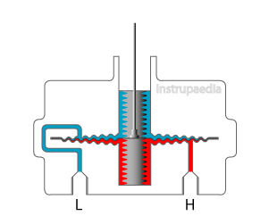
Diaphragm pressure gauges for measuring differential pressure are different from those made for the measurement of relative or absolute pressure. On both sides of the membrane, there is a pressure chamber closed off by a bellows. Each of these pressure chambers is connected to a different pressure which creates a differential pressure across the diaphragm.
The below drawings illustrate the different types of diaphragm gauges. It will be obvious that differential pressure diaphragm gauges are not suitable for highly viscous, impure, or crystallizing media.
Properties of the diaphragm gauge
The pressure ranges of diaphragm gauges fall between 10 mbar (0,145 psi) and 40 bar (580,15 psi).
For smaller measuring ranges (in the order of the mbar), diaphragms are used with a larger diameter. This increases the sensitivity of the diaphragm for small pressure differences and also increases the stroke length. Due to the increased sensitivity, the accuracy will be higher. The large stroke length ensures that the transmission mechanism can be equipped with a lower transmission ratio. The latter is useful since, by very low pressure, the diaphragm exerts less force on the transmission mechanism.
At pressures below 10 mbar, the diaphragm gauge runs up against its limits. To be able to measure such small pressures, the diaphragm should be ultra-thin in order to possess sufficient elasticity, making it no longer reliably stable. The measurement of very low pressures is the scope of the capsule pressure gauge.
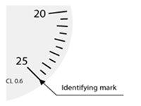
Diaphragm pressure gauges are available in accuracy classes from 0.6 to 1 – 1.6 – 2.5 and 4. As always expressed as a percentage full scale. The accuracy is determined among others by the type of material, the thickness, the waveform, and the diameter of the diaphragm.
The annular clamping of the diaphragm makes these pressure gauges insensitive to vibrations.
Because of their structure, these gauges provide good protection against overpressure, since the diaphragm is pressed against the upper flange when the pressure is too high. By default, these pressure gauges can resist pressures of about 5 times the full-scale value. Compared with the 1.3 times full-scale value overpressure protection of a Bourdon tube pressure gauge, this is so much higher. When the upper flange is provided with matching convolutions to the diaphragm, the overpressure protection may even rise to 100 times the full-scale value.
Protection against corrosive and impure media
Corrosive media could easily impair and even pierce the thin diaphragm if it would not be adequately protected. To protect the diaphragm, special materials in the shape of a foil, such as PTFE, tantalum, Hastelloy, titanium, or gold are glued to the diaphragm. The appropriate protective material must be chosen in function of the corrosive medium.
It is also possible to manufacture the complete diaphragm from the special material if the flexibility of the material is sufficiently large.
When the corrosive medium is very aggressive, the lower flange can also be treated with protective material. In this case, all process wetted parts are protected.
For impure or crystallizing media, designs with an open flange are available.
For sanitary applications, a flush diaphragm is mainly used, as shown in the illustration below. A flush diaphragm has the advantage that it does not contain any “dead” spaces, and it is easy to clean.
Safety precautions
When the diaphragm fails, the process pressure will flow into the case. If the built-up pressure becomes higher than the maximum containable pressure of the casing, the window of the gauge will shatter.
To protect the operator from the emitted high-velocity gas, the pressure gauge is provided with a blow-out device on the back or top. This blow-out device can be a simple plug, blown away when the casing gets overpressurized. This plug must be designed such that the protection becomes active as soon as the pressure in the casing reaches half of the window-burst pressure. This type of protection is designated by the denomination S1.
When the pressure gauge is liquid-filled, a blow-out device is always mandatory.
Datasheet template
An easy configurable Excel template is available for specifying diaphragm pressure gauges. This datasheet is designed to define diaphragm pressure gauges for all kinds of applications.
Datasheet templates for other types of instruments can be found in the datasheet library.
Related topics
Leave a Comment
Your email address will not be published. Fields marked with * are required.