Bellows pressure gauge
Pressure gauge working principle and properties
 17 May 2022
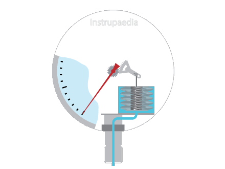
Bellows pressure gauge working principle
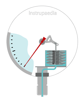
Bellows are thin-walled metallic cylinders, with deep convolutions, of which one end is sealed and the other end remains open. The closed-end can move freely while the open-end is fixed.
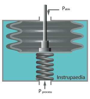
When pressure is applied to the closed-end, such as in the animation below, the bellows will be compressed. The closed-end will move upwards and the link, which is the rod in between the closed-end of the bellows and the transmission mechanism, will go up and rotate the pointer.
“Check out other pressure gauge animations:”
Characteristics of bellows pressure gauges
Compared with diaphragm and capsule pressure gauges, bellows gauges have the advantage of a longer stroke length and they generate larger forces.
The number of convolutions can vary between 5 and 20. More convolutions
The diameter of the bellows determines the force that can be transmitted to the transmission mechanism. Therefore a larger diameter will be chosen for the measurement of very low pressures in order to have sufficient surface area to which the measured pressure can act.
A larger diameter also means higher sensitivity and improved accuracy.
Bellows may be fabricated from different materials. Each of these materials has its own specific stiffness, which is proportional to Young’s modulus of the material and is inversely proportional to the outside diameter and the number of convolutions of the bellows.
The relationship between the pressure exerted on the bellows, and its deflection is linear and is only disrupted when the elastic limit is reached.
The deflection can be expressed as follows:
|
|||
| Where: | δ | = | deflection of the bellows |
| n | = | number of convolutions | |
| Ae | = | effective surface of the bellows | |
| P | = | pressure | |
| R | = | average radius of the bellows | |
| E | = | Young’s modulus | |
| t | = | wall thickness | |
Bellows are sensitive to temperature changes, work hardening, drift, friction, hysteresis, and vibrations.
To compensate for these drawbacks, a bellows is generally used in combination with a calibrated spring.
As an additional advantage, the measuring range can be determined by the choice of the spring. Choosing a strong spring will lead to a large measuring range which makes it possible to measure large pressures with a bellows pressure gauge. For this reason, most bellows gauges are spring-loaded.
The spring also protects the bellows from being completely retracted or stretched beyond the elastic limit and thus extends its lifespan.

Measuring range of bellows pressure gauges
The pressure range is determined mainly by the effective area of the bellows and the spring gradient, and to a lesser extent by the material from which the bellows are made. For higher measuring ranges bellows will be used with a smaller diameter.
This kind of pressure gauges can be used to measure different types of pressure but are generally used for the measurement of low pressures, ranging from vacuum to about 3.5 barg.
Differential pressure gauges consisting of 2 opposing bellows with internal heavy range springs can be used at much higher static pressures (up to 750 barg) with a differential pressure measurement range of 69 bar.
Fabrication of bellows
Bellows are usually made from thin-walled seamless tubes pressed hydraulically, or mechanically roll formed
They can be manufactured from beryllium copper, phosphor bronze, Monel, Inconel, and stainless steel.
The bellows will have good hysteresis properties when using phosphor bronze, while beryllium copper provides better dynamic properties. Stainless steel is used when the bellows come into contact with corrosive media, but it has the disadvantage of being less elastic.
Relative pressure sensors
Bellows may be used both in compression and expansion.
When relatively low pressures are to be measured, the bellows will usually be used in
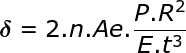
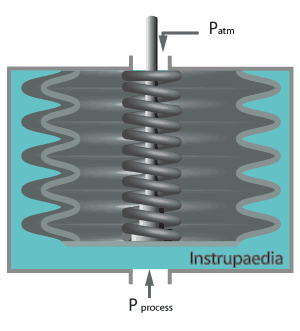
If more significant pressures are to be measured, it is better if the process pressure acts on the outside of the bellows. In this case, the bellows are compressed.
When measuring larger pressures, the bellows are always equipped with a heavy range spring.
In both illustrations, below, the inside of the bellows is at atmospheric pressure whereas the outer side is subject to the process pressure. Both bellows, therefore, work in compression. The only difference between the two is the position of the spring. It can be located either on the inside of the bellows or on the outside.
Such sensors may also be used for the measurement of differential pressure. The only thing required is to replace the atmospheric pressure inside the bellows with a second process pressure.
Also, a compound pressure gauge can be made with a single
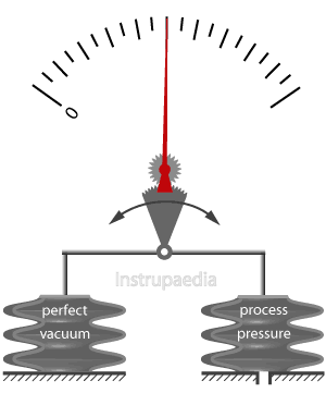
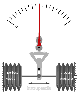
Absolute pressure sensors
To measure absolute pressure we need two bellows. The first one is the reference bellows, which is provided with a perfect vacuum on the inside. The second one is
Since these absolute pressure sensors are generally used to measure low pressures, the bellows are not equipped with calibrated springs and they are used in
The deflection of the bellows is transferred via the transmission mechanism to the pointer.
A change in the atmospheric pressure has no influence on the measurement in this case since the influence of this pressure on the two bellows is equally great.
Absolute pressure sensors exist in two different versions. On the one hand, there is the beam balance principle and on the other hand the opposed principle, as in the illustrations shown below.
Differential pressure sensors
Just as differential pressure can be measured with a single
The low process pressure is connected to the first bellows while the high process pressure is connected to the second bellows.
Both of these process pressures will exert a force on the effective area of the bellows upon which they act. The resultant force rotates the pointer.
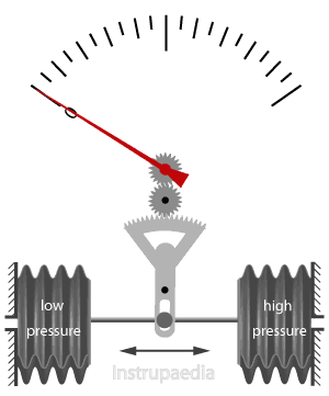
These measurement devices can be designed for the measurement of differential pressures up to 70 bar or more, with an overpressure limit of up to 750 barg static pressure on both sides of the device.
At such high pressures, bellows with a small diameter are preferred, optionally provided with an internal or external spring. The accuracy will be less because of the need for
At high differential pressures, the accuracy is around 1.5% of the measuring range. At lower differential pressures up to 1 bar, accuracies of 0.5% of the measuring range are possible.
Datasheet template
An easy configurable Excel template is available for specifying bellows pressure gauges. This pressure gauge datasheet is designed to define bellows pressure gauges for all kinds of applications.
Datasheet templates for other types of instruments can be found in the datasheet library.
Related topics
Leave a Comment
Your email address will not be published. Fields marked with * are required.