
How to do a pressure calibration
Get a better grip on your process with more accurate pressure measurements
 9 October 2022
Pressure calibration is something that needs to be done from time to time to keep your process running smoothly.
Anyone who is professionally involved with instrumentation will have experienced that measurement signals can deviate over time.
To avoid this deviation, pressure transmitters must be calibrated regularly.
This article will explain how to perform such a calibration.
What is pressure calibration?
Every pressure transmitter senses the pressure and generates an output signal per the design of the pressure sensor’s electronics.
Unfortunately, this pressure output signal will not be accurate forever.
After a certain time, the response of the pressure transmitter will change. This deterioration goes so slow it cannot be felt or visualized as a trend in many cases. Consequently, the process will get affected due to incorrect pressure values.
To overcome this problem, regular preventive maintenance of the pressure transmitter is required, or when any issue is suspected in the pressure transmitter. One of these preventive maintenance actions is the calibration of the pressure transmitter.
During the pressure calibration procedure, actual pressure is applied to the pressure transmitter using a very precise and well-known pressure source. If a problem is found, appropriate action is taken to correct the transmitter output.
After proper calibration of the pressure transmitter, the pressure transmitter electronics will provide an accurate output corresponding to the pressure detected by the pressure sensor.
Things to consider before calibrating a pressure transmitter
Before you start calibrating a pressure transmitter, some basic, but very important things need to be taken care of. It is better to prepare a checklist to prevent problems.
Here are the four things to consider:
- Check the Interlocks associated with the pressure transmitter. If any Interlocks are there, then bypassing the interlock with a proper interlock bypass procedure is a must.
- Check whether the pressure transmitter is used for controlling a control valve. If a control valve is controlled by the pressure transmitter in auto mode, switch the control loop to manual mode. During calibration, the pressure values will vary and if the control valve is in auto mode, it will start to move. This unwanted movement of the control valve will adversely affect the process.
- Also, check whether the pressure value is used by other parts of the plant. If the pressure values of the pressure transmitter under calibration are used by other parts of the plant, inform the relevant operators to avoid problems.
- Some critical pressure transmitters could be configured in a text messaging system. That system will send a text message to predefined phone numbers when there is a high or low-pressure reading. So, inform those people if such a possibility exists to avoid panic situations.
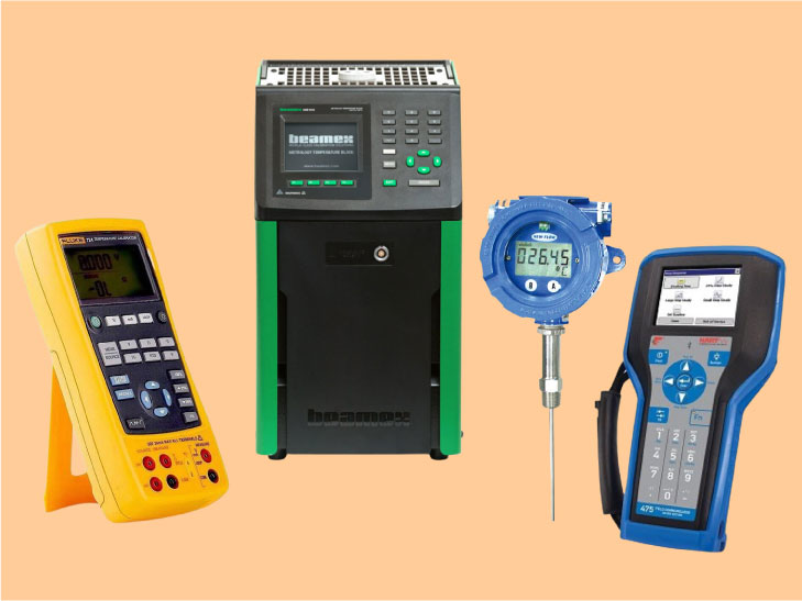
Tools and tackles needed for the pressure transmitter calibration job
- A digital multimeter capable of measuring DC voltage and milliampere.
- A pressure gauge with a range that is 1.5 times greater than that of the pressure transmitter.
- A pressure-generating device such as a pressure pump, pressure calibrator, or dead weight tester, depending on the range of the pressure transmitter.
- A HART communicator
- Both 1/4″ and 1/2″ temporary tubes.
- Various fittings of different sizes for connecting the temporary tube to the pressure transmitter.
Make sure the digital multimeter, HART communicator, and pressure-generating device are calibrated. The digital multimeter and the pressure-generating device must have a greater accuracy (minimum 4 times) than the accuracy required by the pressure transmitter. The pressure gauge must be calibrated with the main calibration device which is 4 times more accurate than the pressure transmitter.
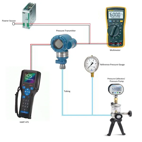
Pressure transmitter calibration procedure with pressure calibrator
For this calibration, we will use a hand pump to provide the test pressure.
Both pneumatic and hydraulic hand pumps are available. The choice between the two depends on the pressure you want to test at:
- Pneumatic hand pumps can be used up to about 600psi (41bar)
- Hydraulic hand pumps operate at pressures up to approximately 10000psi (690bar)
Below mentioned steps can be followed to do the calibration of a pressure transmitter:
- Obtain a proper permit to work and do a proper risk assessment.
- Bypass all interlocks with a proper interlock bypass procedure.
- Put the control valve or ON-OFF valve in manual mode if any control valve or ON-OFF valve is being controlled by the pressure transmitter to be calibrated.
- Inform all the operators (also at other parts of the plant) who are using the pressure transmitter signal and disable the alert system, if any exists.
- Ask the operation department to isolate the root valve and put a proper isolation tag on the root valve for identification purposes.
- Now the pressure transmitter needs to be drained for removing the material between the root valve and the pressure transmitter. If the pressure transmitter is used for measuring the pressure of a fluid that is toxic, flammable, or dangerous to humans or the environment, then do an arrangement for a closed drain. If the pressure transmitter is used for a safe fluid like regular water or air, then we can directly open the pressure transmitter to the atmosphere.
- After the material between the root valve and the pressure transmitter is removed, open the pressure transmitter to the atmosphere. We can remove the vent plugs from the vent ports behind the valve manifold. In this condition, the pressure transmitter should show 0 kg/cm2 or 0 psi depending on the unit configured. This is the case for a gauge pressure transmitter. An absolute pressure transmitter will show 1 kg/cm2 or 14.696 psi depending upon the type of unit configured. This step helps to check the pressure transmitter’s response at atmospheric pressure conditions.
- Now we need to check the response of the pressure transmitter with actual pressure. So, connect the hand pump to the pressure transmitter. Use proper fittings that do not cause damage to the pressure transmitter and do not leak while pressurizing the pressure transmitter. Configure the pressure range of the pressure generator to the same measurement range as the pressure transmitter.
- Also, connect a pressure gauge with the correct range (usually 1.5 times that of the pressure transmitter) to the hand pump and the pressure transmitter. This is done to double-check the pressure exerted by the hand pump.
- Connect a digital multimeter to the 24 VDC supply loop of the pressure transmitter if the pressure transmitter is operating at 4 mA to 20 mA. If the Foundation Fieldbus protocol is used, you do not need to connect a digital multimeter.
- Connect the HART communicator to the pressure transmitter.
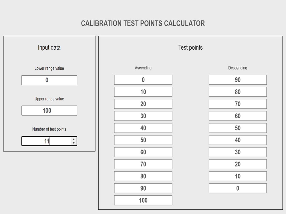
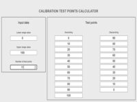
- Check the measuring range of the transmitter and calculate 5 calibration test points. These calibration points will correspond to 0%, 25%, 50%, 75%, and 100% of the range. You can find the range by looking into the configuration settings of the transmitter or finding it on the datasheet. The 5 test points can easily be calculated with this calibration test points calculator.
- Use the hand pump to start applying pressure to the transmitter. First, apply a 0% value. Check the value on the hand pump, the pressure transmitter, and the double-check gauge. All the values should be equal to the 0% value. Now confirm the value indicated on the operator’s HMI or the system. If any discrepancy is found, then troubleshoot it. In many cases, the issue is a value mismatch between the field and the HMI. There could be many reasons for this difference. Some reasons are listed below:
- The range of the pressure transmitter is different from the range configured in the system. For example, the range of the transmitter is 0 to 100, while the range in the system is 0 to 50. So when the field device shows 50, the system shows only 25. Changing the range to the correct one will help solve this problem.
- Instead of 4 to 20 mA, a range of 0 to 20 mA or some other range is sometimes configured in the field. But in the system, the range is 4 to 20 mA. So due to the difference in the mA range, the value will also be different. Or on the system side, the mA range is incorrect according to the datasheet. Changing the incorrect mA range to the correct mA range can solve this problem.
- The transmitter is having a pressure-sensing problem. So, calibration is needed.
- If an intermediate system is used to transfer the data, the range may also be misconfigured in that system. Often data is passed from the ESD control system to the DCS. So due to incorrect range configuration on either side, the value will be different.
- Apply 25%, 50%, 75%, and 100% pressure values to the pressure transmitter. Wait a few seconds after applying the value so that the system becomes stable at that point. Check for leaks in between, if the readings do not match, or if the pressure is unstable. Record all the respective measured values in the calibration sheet.
- Similarly, start from 100% by applying descending values in 25% increments and record all measured values.
- Calculate the error% with the formula :
(measured value – reference value) / reference value *100 - If the error% is within the limits mentioned in the datasheet, then the pressure transmitter is ok.
- If the error% is greater than the limit, then zero and span calibration is needed.
- For a zero calibration, use the hand pump to apply the 0% of range value. Go to the calibration menu in the HART communicator and press the “Zero Trim” button. Wait for a few seconds till a success message is displayed.
- Use the hand pump to apply the 100% of range value. Again, go to the calibration menu in the HART communicator and press the “Span Trim” button. Wait for a few seconds till a success message is displayed.
(Some old transmitters have a zero and span setting screw. So, set zero and span from the screws one by one after applying the respective pressures) - After the pressure transmitter has been adjusted, it is necessary to reverify it. So, use the hand pump again to apply 0%, 25%, 50%, 75%, and 100% of range values. Note down all the values as you did previously. Also, check the values in decreasing order in steps of 25%.
- Again, calculate the error%. The error% should be within the maximum allowable limit. If the error% is still too high, then do the calibration of the pressure transmitter one more time. Follow all the steps from step 18 onwards one more time.
- If the error% still exceeds the limits, the pressure transmitter must be replaced.
- If the calibration was successful, apply a calibration sticker to the pressure transmitter.
- Restore all the bypassed interlocks after informing the process operators. If the loop is still in manual mode, ask them to put the loop back in auto mode. Inform other plants about the completion of the calibration job. Also, restore the messaging system if changes have been made or notify all involved persons of the completion of the pressure calibration.
Pressure transmitter calibration procedure with dead weight tester
A dead weight tester is generally used in calibration laboratories. Dead weight testers have 5 to 10 times higher accuracy than a pressure calibrator or a pressure pump.
The accuracy to be obtained from a dead weight tester is about 0,006% of reading.
With a dead weight tester, discs with a very accurate weight are stacked on top of a piston that is filled with fluid. The piston converts the mass of the discs into an extremely precise fluid pressure.
Different types of fluids are available. Some dead weight testers work with air, others with oil or water. The choice of fluid depends on the test pressure that the dead weight tester must be able to supply.
Broadly speaking, the choice comes down to this:
- air: up to 14MPa (140bar)
- water: up to 70MPa (700bar)
- oil: up to 140MPa (1400bar)
Special hydraulic dead weight testers can even produce pressures up to 400MPa (4000bar) or more.
The steps below can be followed to perform the calibration of a pressure transmitter using a dead weight tester.
Attention: If the pressure transmitter is used to measure oxygen gas or any other chemical which can react adversely with the oil of the dead weight tester, then do not use the dead weight tester.
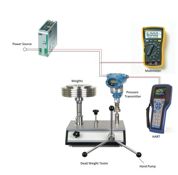
- Set up the dead weight tester, pressure transmitter, 24Vdc power supply, HART communicator, and multimeter as in the picture above.
- Before connecting the power supply directly to the pressure transmitter, check the output voltage and set it according to the requirements of the pressure transmitter. Use a 250 Ohm resistor in series in the case of a HART protocol pressure transmitter and a Foundation Fieldbus (FF) power module in the case of an FF-type pressure transmitter. Now, turn ON the power.
- Check the oil level inside the dead weight tester.
- Put the appropriate weight on the weight platform according to the dead weight tester’s chart showing weight versus pressure.
- Use the hand pump to apply pressure until the weight on the weight platform begins to float between the red and blue lines.
- Check the value on the pressure transmitter and note it down.
- Check all values at 25% intervals, starting from 0% to 100%, and vice versa from 100% to 0%. This leads to a 5-points calibration. You can calculate the pressure value of these 5 test points by using our calibration test points calculator.
- Calculate the error% as we did in the case of a pressure transmitter calibration using a pressure calibrator.
- If the maximum value of the error% is more than the maximum allowable error%, perform a zero and span calibration.
- Repeat step 7 and recalculate the error.
- If the maximum error% is still greater than the allowable error, try a zero and span trim one more time. If the error remains too high, replace the pressure transmitter.
- After calibration, gently clean the sensor unit of the pressure transmitter with a suitable cloth to remove the oil on the sensor side.
How to choose which calibration method to use?
The method of performing a pressure calibration is highly dependent on the desired accuracy of the pressure transmitter.
Hand pumps have a maximum accuracy of 0,1% of reading, dead weight testers go as far as 0,006% of reading.
Based on the fact that calibration equipment must be at least 4 times more accurate than the device to be calibrated, we arrive at the following conclusion:
- with a hand pump, pressure transmitters can be calibrated that must be accurate to a maximum of 0.5%
- with a dead weight tester, we can calibrate pressure transmitters to an accuracy of 0.025%
Pressure transmitters used in critical services or used for invoicing must have very high accuracy and should be calibrated with a dead weight tester.
If only a few of these high-accuracy applications need to be calibrated each year, it may be better to have this performed by an external test lab.
If the company has many of these demanding applications, it may be more cost-effective to purchase a dead weight tester and perform the tests in-house.
Keep in mind that for some applications it is required that the test lab is ISO/IEC 17025 accredited.
These high accuracies are not always necessary to control a process. Usually, the repeatability of the measurement is much more important. Many pressure transmitters for process controls only need an accuracy of 0.5% or 1% and can therefore be calibrated with a hand pump.
In addition to the two categories already mentioned, there is a third category of pressure transmitters where accuracy does not play a major role. These are the pressure transmitters that only serve as a visual indication of the process pressure. Just to have an idea of the pressure in the pipe or vessel. They only need an accuracy between 1% and 5%. In this case, it may not even be necessary to calibrate them.
Why does a pressure transmitter need to be calibrated?
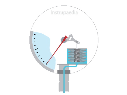
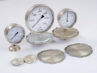
A pressure transmitter has a diaphragm or pressure sensor assembly to measure the pressure and an electronic circuit to convert the sensor signal to an output signal.
A membrane or pressure sensor assembly is nothing more than a mechanical device, subject to mechanical stress, abrasion, chemicals, or degradation of the fill fluid. So, it is obvious that all this will have an impact on the electrical properties of the sensor, e.g. a change in capacitance or resistance, whatever measuring principle is used.
Also, the transmitter is installed in the field and is powered on for 24×7 hours. The electrical current constantly flowing through the electronic components will slightly alter the characteristics of these components over time. Temperature variations, moisture, and vibration will also add to the electronics’ aging. The output signal strength can vary depending on how the electronic components react to this aging effect.
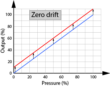
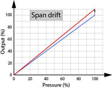
Under the influence of the above effects, the accuracy of a pressure transmitter will slowly deteriorate. This slow process of deterioration is called drift. There are two types of drift:
- Zero drift: here the zero point will shift and the entire calibration curve moves up or down with it.
- Span drift: here the shift is in the slope of the curve, and the zero point remains in place.
Zero drift is more common than Span drift.
So, over a period of time, the response of the transmitter will change because of the aging effects on the diaphragm as well as the electronic circuits. The measurement starts losing reliability, the process is less under control and safety becomes less guaranteed.
Hence it becomes necessary to validate the response of the transmitter. If during validation, any deviations are found, then calibration of the transmitter is necessary to avoid problems or measurement inaccuracies. A calibrated pressure transmitter can help increase process efficiency as well as prevent unwanted shutdowns and fatalities.
How often should you calibrate a pressure transmitter?
The calibration frequency of a pressure transmitter is determined by the process criticality. In general, pressure transmitters are calibrated with an interval of 3 to 5 years. In case of malfunction or incorrect operation, the pressure transmitter must be calibrated.
Related topics
3 Comments
Leave a Comment
Your email address will not be published. Fields marked with * are required.


Very nice
Thanks
this is very helpfull, thank you for knowledge sir