According to IEC 60751 or ASTM 1137 accuracy classes
With this tolerance testing tool, you can check the accuracy of RTD sensors according to the standards IEC 60751 and ASTM 1137 and the accuracy class of your RTD sensor.
The tool will tell you if your sensor is still ok (PASS) or needs to be replaced (FAIL).
How to use the tolerance testing tool
First, you have to tell the tolerance testing tool what kind of RTD sensor you’re going to test. Therefore, fill in the following fields:
TAG number
If you want to keep a track record of present and future calibrations of your temperature sensor you should fill in the TAG number of your device. Select the field by clicking into the empty box, then type your TAG number. This number will be stated on the printout of the test results.
Test date
Enter the date on which the test will be performed. You can fill in the date in two different ways:
Clicking in the field highlights the first two digits for entering the day of the month. Fill in the date according to the format indicated.
By selecting the calendar via the calendar symbol on the right of the field. First, select the year, then the month, and the day.
Standard
Select the standard to which the sensor is built. You can choose between IEC 60751 and ASTM 1137.
Class
Select the accuracy class of the temperature sensor. The choice of accuracy class depends on the standard you have selected. The following choices are possible:
IEC 60751
Class AA
Class A
Class B
Class C
ASTM 1137
Class B
Class C
STD Accuracy
If you made a valid choice for the standard and its accuracy class, this field will automatically indicate the accuracy to be achieved. If you have chosen the wrong combination for the standard and the accuracy class, the text ‘ combination not defined ‘ will appear in this field.
Ref. T° (°C)
While performing the test, enter here the stabilized temperature indicated by the temperature bath or the reference temperature sensor.
UUT T° (°C)
UUT stands for Unit Under Test. The temperature indicated by the sensor being checked must be entered here.
Error (°C)
This is an automated field that calculates the temperature deviation of the tested sensor. Error = UUT T° – Ref. T°
STD Err (°C)
This is an automated field that calculates the maximum allowable error according to the chosen standard and accuracy class. It uses the formula indicated in the STD Accuracy field in which it inserts the temperature of the test point entered in the field Ref. T°.
Status
This is an automated field with only two possible outcomes: PASS or FAIL
When it says PASS, your sensor is good to go. If it says FAIL, your sensor is inaccurate and should be replaced.
Add test point
Click this button if you want to add another test point. The next test point will be added underneath the already indicated test points.
Print results
Click this button after you have completed all your test points. Your test results will be printed.
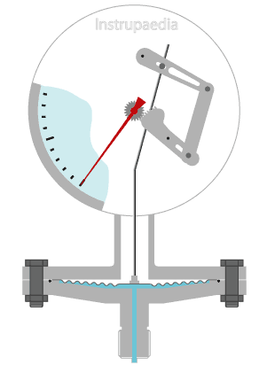
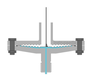
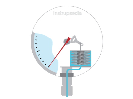
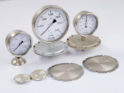
The diaphragm pressure gauge consists of a circular membrane, made from sheet metal of precise dimensions, which can either be flat or corrugated.
The diaphragm is mechanically connected to the transmission mechanism which will amplify the small deflections of the diaphragm and transfer them to the pointer.
The animation below shows the pressure gauge working principle. You can see the movement of the diaphragm and the functioning of the transmission mechanism.
The process pressure is applied to the lower side of the diaphragm, while the upper side is at atmospheric pressure. The differential pressure arising across the diaphragm lifts the diaphragm and puts the pointer in motion.
The deflection of the diaphragm is very small (+/- 1 mm) making it necessary to use a high-ratio multiplying movement to rotate the pointer along the full length of the scale. The actuation of such a high-ratio transmission mechanism is possible because diaphragm deflection can generate large forces.
Flat and corrugated diaphragms
The diaphragm must be made in such a way that the deflection is linear, i.e. that a similar increase in the pressure should always correspond to a similar deflection of the diaphragm.
A flat diaphragm made of metal will only be linear when the deflection is very small, too small to have sufficient movement of the pointer.
At larger deflections, a flat diaphragm loses its linearity since more and more stress will occur in the diaphragm. The diaphragm becomes increasingly stiffer due to the growing tension, resulting in less deflection of the diaphragm for a similar increase in pressure.
A flexible material, such as a thin sheet of nylon can, however, serve as a flat diaphragm. The diaphragm will then be opposed by a calibrated spring which ensures the linearity and pushes the diaphragm back to its starting position.
For industrial applications, usually corrugated metal diaphragms are used. The corrugations ensure that the diaphragm will be more elastic and they are arranged such that the deflection of the diaphragm is linear. There are different types of corrugated profiles as you can see in the figure below.
Common convoluted diaphragms
Diaphragm pressure gauge application
Diaphragm pressure gauges are used for relative pressure as well as for vacuum, compound, and differential pressure applications.
Due to the presence of a diaphragm, these gauges are extremely suitable for use on viscous media. For corrosive gases and liquids, the diaphragm may be coated or covered with a foil.
By default, these diaphragm gauges are provided with a male threaded connection.
For highly viscous, impure, or crystallizing media, however, it may be necessary to use an open connection flange to prevent clogging of the process connection. Open connection flanges are available from DN15 to DN80. The most common sizes are DN25 and DN50.
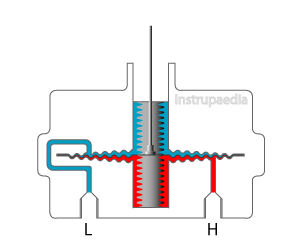
Diaphragm pressure gauges for measuring differential pressure are different from those made for the measurement of relative or absolute pressure. On both sides of the membrane, there is a pressure chamber closed off by a bellows. Each of these pressure chambers is connected to a different pressure which creates a differential pressure across the diaphragm.
The below drawings illustrate the different types of diaphragm gauges. It will be obvious that differential pressure diaphragm gauges are not suitable for highly viscous, impure, or crystallizing media.
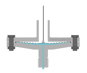
Relative pressure, vacuum and compound
Differential pressure with protection against overpressure
Properties of the diaphragm gauge
The pressure ranges of diaphragm gauges fall between 10 mbar (0,145 psi) and 40 bar (580,15 psi).
For smaller measuring ranges (in the order of the mbar), diaphragms are used with a larger diameter. This increases the sensitivity of the diaphragm for small pressure differences and also increases the stroke length. Due to the increased sensitivity, the accuracy will be higher. The large stroke length ensures that the transmission mechanism can be equipped with a lower transmission ratio. The latter is useful since, by very low pressure, the diaphragm exerts less force on the transmission mechanism.
At pressures below 10 mbar, the diaphragm gauge runs up against its limits. To be able to measure such small pressures, the diaphragm should be ultra-thin in order to possess sufficient elasticity, making it no longer reliably stable. The measurement of very low pressures is the scope of the capsule pressure gauge.
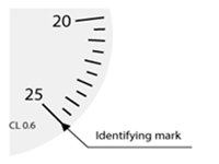
Diaphragm pressure gauges are available in accuracy classes from 0.6 to 1 – 1.6 – 2.5 and 4. As always expressed as a percentage full scale. The accuracy is determined among others by the type of material, the thickness, the waveform, and the diameter of the diaphragm.
The annular clamping of the diaphragm makes these pressure gauges insensitive to vibrations.
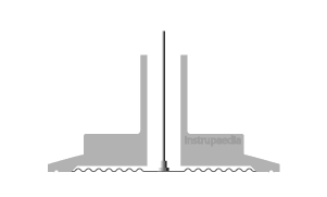
Because of their structure, these gauges provide good protection against overpressure, since the diaphragm is pressed against the upper flange when the pressure is too high. By default, these pressure gauges can resist pressures of about 5 times the full-scale value. Compared with the 1.3 times full-scale value overpressure protection of a Bourdon tube pressure gauge, this is so much higher. When the upper flange is provided with matching convolutions to the diaphragm, the overpressure protection may even rise to 100 times the full-scale value.
Upper flange with matching convolutions
Protection against corrosive and impure media
Corrosive media could easily impair and even pierce the thin diaphragm if it would not be adequately protected. To protect the diaphragm, special materials in the shape of a foil, such as PTFE, tantalum, Hastelloy, titanium, or gold are glued to the diaphragm. The appropriate protective material must be chosen in function of the corrosive medium.
It is also possible to manufacture the complete diaphragm from the special material if the flexibility of the material is sufficiently large.
When the corrosive medium is very aggressive, the lower flange can also be treated with protective material. In this case, all process wetted parts are protected.
For impure or crystallizing media, designs with an open flange are available.
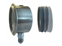
For sanitary applications, a flush diaphragm is mainly used, as shown in the illustration below. A flush diaphragm has the advantage that it does not contain any “dead” spaces, and it is easy to clean.
Flush diaphragm for sanitary applications
Safety precautions
When the diaphragm fails, the process pressure will flow into the case. If the built-up pressure becomes higher than the maximum containable pressure of the casing, the window of the gauge will shatter.
To protect the operator from the emitted high-velocity gas, the pressure gauge is provided with a blow-out device on the back or top. This blow-out device can be a simple plug, blown away when the casing gets overpressurized. This plug must be designed such that the protection becomes active as soon as the pressure in the casing reaches half of the window-burst pressure. This type of protection is designated by the denomination S1.
When the pressure gauge is liquid-filled, a blow-out device is always mandatory.
Datasheet template
An easy configurable Excel template is available for specifying diaphragm pressure gauges. This datasheet is designed to define diaphragm pressure gauges for all kinds of applications.
Datasheet templates for other types of instruments can be found in the datasheet library.
3 Types of pressure and units from around the world
What is pressure?
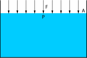
By definition, pressure is described as the amount of force applied perpendicular to a surface per unit of area.
It can be calculated by the following formula:
P =
FA
where:
P
=
Pressure
F
=
The resultant force
A
=
The surface subjected to the force
Atmospheric pressure on the surface of a liquid
How is pressure physically created?
One way to look at pressure is to see it as the result of the weight of all stacked molecules on top of a surface. This approach fits best for solids and liquids.
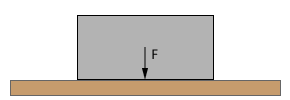
A solid block creates pressure on a surface by its weight
The figure above is showing a surface with a solid block on top of it.
Every molecule of that block has weight because gravity is pulling on it. Since weight is a downward force, every molecule will exert a small force on the surface.
The resultant force of all these small forces is creating the pressure.
When using this approach for gases, one could argue that the gas molecules are not stacked since they are freely floating around. So, how can they exert a force on that surface?
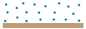
Molecules create pressure on a surface with every impact
The molecules of a gas are in constant movement. As they move, they have momentum and kinetic energy. Frequently they will collide with each other and with the surface of an object.
With every collision with the surface, the molecules pass on momentum to that surface. This generates a force perpendicular to that surface.
The sum of the forces of all these colliding molecules is creating the pressure.
What are the different types of pressure?
There are three types of pressure:
absolute pressure
gauge pressure
differential pressure
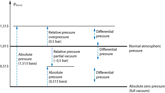
The difference between these three is the reference point that is chosen as the zero point on the scale. For absolute pressure, the perfect vacuum was chosen as the reference point, while for gauge pressure the reference point is atmospheric pressure. For differential pressure, there is no fixed reference point because two different pressures are compared.
The following drawing shows the different types of pressure. The starting point of each arrow coincides with a chosen reference point. Note that absolute pressure and differential pressure are always positive, while relative (gauge) pressure can also be slightly negative. In the latter case, we also call it a partial vacuum. Theoretically, the maximum partial vacuum is -1,013 bar gauge, which corresponds to a perfect vacuum.
A pressure measurement is, in principle, always comparing the pressures between two different places.
For absolute pressure, the comparison is made between a location at a certain pressure and another location at absolute vacuum.
Likewise for relative (gauge) pressure where the comparison will be done with a location at normal atmospheric pressure (1013 mbar at sea level).
The measurement of differential pressure is comparing the pressures between two random locations.
Pressure measurement devices are specially designed for measuring these three different types of pressure and can, therefore, be classified accordingly.
Absolute pressure
Measuring something is done by comparing it to a well-known point of reference. For absolute pressure, the point of reference is the perfect vacuum. This point has been chosen because it is the lowest possible pressure. In particular, there is no pressure at all.
A perfect vacuum would mean that all particles have been removed from a closed volume. In this volume, which is then completely empty, pressure cannot be present.
As already said, absolute pressure is always a positive number. Negative numbers are impossible because there is no pressure below the perfect vacuum.
Gauge pressure (relative pressure)
Instead of comparing the measured pressure to a perfect vacuum we will now compare it to the standard atmospheric pressure at sea level. The latter amounts to 1013.25 mbar (14.696 psi).
The difference between absolute and gauge pressure, simultaneously measured at the same place, is always about 1 bar (14.50 psi).
Gauge pressure, sometimes also called relative pressure, can assume both positive and negative values. For positive values, it is called overpressure. The measured pressure is then higher than the standard atmospheric pressure and is equal to the absolute pressure minus atmospheric pressure.
Po = Pabs – Patm
If the measured gauge pressure is negative, it is called underpressure or partial vacuum. The measured pressure is then lower than the standard atmospheric pressure and is found by subtracting the absolute pressure from the atmospheric pressure.
Pu = Patm – Pabs
By mentioning that it is a partial vacuum we do not need to use the minus sign. If a vacuum cleaner operates at an absolute pressure of 0,8 bar, we could also say that it operates at 0,2 bar underpressure.
Differential pressure
Sometimes it is necessary to measure the pressure difference between two different points. When one nor the other point is a reference point, e.g. a perfect vacuum or the standard atmospheric pressure, it is called a differential pressure.
In theory, one could argue that absolute and gauge pressures are as well differential pressures since we also measure the pressure difference between two points. However, a differential pressure is only saying something about the difference in pressure between two points. It gives no information about the level of pressure in each of these two points.
For example, 3 bar differential pressure between points A and B doesn’t say anything about the amount of pressure at points A and B, nor does it say anything about which point is at the highest pressure.
Are there any other types of pressure?
All pressure types we have discussed so far are based on the choice between the two conventional reference points or the comparison between two pressures.
However, there are certain kinds of pressure that are given a specific name to indicate the meaning of the pressure. Some examples of common pressures are:
Vacuum pressure
Atmospheric pressure
Hydrostatic pressure
Dynamic pressure
This has nothing to do with their relationship to a certain type of pressure since they can all be expressed as one of the three types of pressure.
So, no there are no other types. There are only other pressures with a specific name.
Below is a description of these common specific pressures.
Vacuum pressure
Strictly speaking, a vacuum is a space where the absolute pressure is zero. This can only be achieved if all particles are removed from that space. In other words, the space is really empty. The perfect vacuum is only theoretically possible. It will never be technically possible to remove all the particles in a closed volume.
A vacuum doesn’t need to be perfect to be called a vacuum. In practice, a vacuum will only be partially achieved. It is therefore also referred to as a partial vacuum. In general, we speak about a vacuum when the pressure is lower than the atmospheric pressure.
A high vacuum means that the absolute pressure is very low.
In order to create a vacuum, use is made of a vacuum pump. With this pump, the particles present inside a closed volume will be sucked out as much as possible. The capacity of the vacuum pump determines the level of the vacuum.
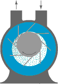
An example of a vacuum pump, which is used quite a lot in the industry, is the liquid ring vacuum pump. An eccentric impeller rotates in a pump housing, without making contact with this casing. Water is injected into the pump housing but insufficient to completely fill the pump. By centrifugal acceleration, the water forms a liquid ring against the inner wall of the pump casing. If sufficient water is injected, the liquid ring will provide a good seal between the impeller and the pump housing. Since the impeller is eccentrically arranged, cells of different sizes occur between the vanes. These cells form compression chambers. Where the cells are largest, the gas particles are sucked in, and where the cells are smallest, they are forced to the outside. With this kind of pump, a maximum of 33 mbar absolute (0.4786 psi absolute) can be achieved.
Vacuum pump
Atmospheric pressure
The atmospheric pressure sometimes referred to as barometric pressure, is caused by the weight of all the molecules in the atmosphere. The accumulation of molecules in the air ensures that the highest pressure occurs at the bottom of the atmosphere.
The atmospheric pressure, however, is not a constant but a variable value. The conditions in the atmosphere of our Earth are constantly changing. Influenced by the sun the air heats up, at night it cools off again. The humidity varies with the weather. The density of the air changes by high or low pressure areas. All of these influencing factors ensure that atmospheric pressure never remains the same in one place.
For the measurement of gauge pressure, this leads to a problem because the pressure to be measured is compared to the atmospheric pressure.
To obtain an unambiguous measurement of the gauge pressure, a standard atmospheric pressure has been introduced. As a reference, the average atmospheric pressure at sea level has been chosen, which meets the following conditions:
Expressed in SI units
Patm = 1013,25 mbara
t = 15 °C
ρ = 1,226 kg/m³
r = 287,1 J/(kg K)
Expressed in customary units
Patm = 14,696 psia
t = 59 °F
ρ = 0,002377 slugs/ft³
r = 1716,49 ft lb/slug °R
Patm : absolute pressure
t : temperature
ρ : density
r : specific gas constant
Hydrostatic pressure
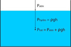
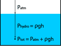
The term hydrostatic pressure is mainly used in fluids. It is the pressure at a given depth in the fluid caused by the weight of the column of liquid above it.
The hydrostatic pressure will depend on the density of the liquid, the gravitational constant and the height of the liquid column.
Hydrostatic pressure is a gauge pressure type and can be calculated with the following formula:
Phydro = ρgh (relative pressure)
If we also take into account the atmospheric pressure above the liquid surface, we find the total pressure:
Ptot = Patm + ρgh (absolute pressure)
As the atmospheric pressure is now accounted for in the equation, we are referencing to a perfect vacuum and so the total pressure becomes an absolute pressure.
Dynamic pressure
Dynamic pressure is one of the terms of Bernoulli’s equation. For incompressible fluids, this equation says that for steady flow along a streamline, the sum of pressure energy, kinetic energy, and potential energy remains constant.
The dynamic pressure is that part of the equation which represents the kinetic energy.
It is a pressure that is created by the kinetic energy of the molecules of a fluid when flowing for example through a pipe.
Dynamic pressure can be expressed with the following formula:
q =
12ρv2
where:
q
=
Dynamic pressure
ρ
=
Fluid mass density
v
=
Flow speed
Pressure units across several continents
Around the world, pressure is expressed in different units.
In the European Union, we are using the SI system as a legal standard. All physical quantities of products should be in line with the European directive 80/181/EEC (EU Metric Directive) and expressed according to this system. In this way, the pressure is expressed in Pa (Pascal) or bar, where 1 bar = 105 Pa. Older units such as mH2O (meter water column) or mmHg (millimeters of mercury), must not be used in the European Union since 31 December 1977.
In the United Kingdom, the psi (pounds per square inch) is still often used, with 14.5 psi ≈ 1 bar, but is now being switched more and more to the bar pressure unit. To the extent that it now mostly replaces the psi as the primary pressure unit.
In the United States, the psi is still the main unit for measuring pressure. Almost all pressure gauges indicate the pressure in pounds per square inch.
In Asia, especially the units MPa (megaPascal) and kg/cm² (kilograms per square centimeter) are used.
In the table below you will find a few other units and their conversion factors to kPa and bar.
Units
kPa
bar
1 kPa
1
0,01
1 MPa
1000
10
1 bar
100
1
1 mbar
0,1
0,001
1 atm
101,32500
1,01325
1 mH2O
9,80665
0,0980665
1 mmHg
0,133322368
0,00133322368
1 psi
6,89475729
0,0689475729
1 inH2O
0,249082
0,00249082
1 kg/cm²
98,0665
0,980665
How the unit of pressure refers to the type of pressure
Expressing a pressure with a unit in its basic notation, such as Pa, bar of psi, doesn’t make much sense if you don’t know which type of pressure is referred to.
Sometimes you can guess the type of pressure based on the context, but usually, doubts will remain. If you have guessed incorrectly, serious errors may occur.
It is therefore always a good practice to indicate the type of pressure after the unit, meaning that the words ‘absolute’, ‘gauge’ or ‘differential’ should be written after the unit of pressure. Pressure could then be expressed as e.g. bar gauge or psi absolute.
Often, you will find a pressure unit followed by a suffix such as ‘g’, ‘a’ or ‘d’ (or written in capital letters) as in barg, psia or kPaD where ‘g’ stands for gauge, ‘a’ for absolute and ‘d’ for differential. The suffix is also sometimes noted in parentheses, e.g. bar(g).
Although these suffixes are still widely used, they are deprecated and no longer supported by international standards.
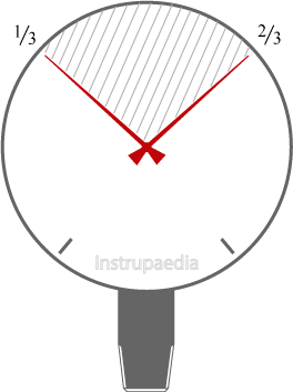
The scale range must be chosen so that the measured process pressure is between 1/3 and 2/3 of the scale range. In this area, the gauge reaches its highest accuracy. As a rule of thumb, you can say that the measurement range should be two times larger than the operating pressure.
Choosing a too small measurement range will result in a pressure gauge that is always working in the last third of his scale. This can lead to metal fatigue of the pressure-responsive element because it is under constant high stress. Occasional overpressure is another reason for not choosing a too small measuring range.
The choice of a too large measuring range will, in turn, lead to an indication within the first third of the scale, where the accuracy is reduced.
Ideal readout range
Ensuring a working pressure between 1/3 and 2/3 of the scale range has the effect that pressure gauges according to ASME B40:100 or EN837, will reach their highest measurement accuracy. It also ensures longer life of the pressure gauge, especially when the process is subject to cyclic pressures.
Tip 2: The scale unit
There are numerous units available for measuring pressure. A small selection from the range of possibilities: bar, mbar, Pa, kPa, MPa, psi, mmH2O, inHg …
The choice of the unit depends, among other things, on the place or country where the gauge is installed.
In Europe, the pressure is very often expressed in bar or mbar, although for the measurement of 3 to 15 psi pneumatic control signals also the unit psi can be used. Pressure gauges with a double scale can be very useful in this case. For example, one scale can be displayed in psi, and the other in bar.
Units such as psi and inHg are widely used in the US while in Asia often the kg/cm², or MPa is used.
Tip 3: The accuracy of the measurement
The accuracy is chosen according to the application and can vary from 0.1 to 5%. If the intention is only to have a rough idea of the pressure at a specific position in the process, it is not necessary to have high accuracy. It is sufficient to choose the accuracy for this purpose between 1.6 and 5% according to the EN837 standard. For manometers designed according to ASME B40.100, this will then be 2/1/2 to 5/5/5.
An example is a pressure gauge at the discharge of a centrifugal pump which only serves to know if the impeller is still intact. Due to an abrasive medium, an impeller may erode, leading to less pressure build-up at the discharge.
The choice is made to an accuracy of between 0.1 and 1% (both according to EN837 as according to ASME B40.100) when it is important to know the exact pressure. Be aware that electronic pressure transmitters can achieve higher accuracies than gauges. If the highest accuracy of a pressure gauge is not enough then you better opt for an electronic pressure transmitter.
Tip 4: The size of the dial
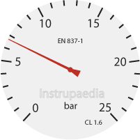
The selection of the dial size depends on the desired accuracy and the application for which the pressure gauge is used. A dial with a larger diameter has more intermediate graduations so that the measured pressure can be read more accurately. Pressure gauges with a larger diameter will generally have a higher accuracy class.
reading 6.8 while…
…it really is 6.7
The reason why a pressure gauge is necessary may also have an influence on the dial size. A larger diameter (eg 160mm) can be useful to read the measured pressure from a certain distance. Pressure gauges to be installed in a cabinet or those used to measure inlet, outlet or set pressures of pneumatic control equipment will be mostly selected small (eg 63mm).
Tip 5: The material of the pressure responsive element
The choice of the material depends on the process medium, but also on the magnitude of the pressure to be measured.
If you want to measure the pressure of an aggressive or corrosive medium, it is best to contact the manufacturer of the gauge to select suitable material for the sensing element.
In many cases, stainless steel will be used for the sensing element, but it is not suitable for all kinds of process media. For example, when the fluid contains free chlorine ions, stainless steel will be corroded.
Possible options are a Bourdon tube made of Hastelloy C276 or tantalum, but make sure not to overkill by choosing the highest quality if not absolutely necessary. Some of these special metals can be very expensive, especially for thick-walled Bourdon tubes suitable for the measurement of high pressures. The mass of these tubes may become quite large.
Depending on the pressure to be measured, a chemical seal may be a possible alternative. The Bourdon tube may then be made of a less expensive type of metal while a suitable type of metal, which is resistant to the process medium, is chosen for the diaphragm. Having only the diaphragm made of an expensive metal will result in a cheaper pressure gauge as a whole since the diaphragm has a much lower mass than the Bourdon tube.
Tip 6: The process connection
There are many types of process connections, but they are mainly divided into three categories: threaded, flanged, and clamped connections. The choice of the process connection is sometimes not easy.
From time to time there’s a lot of consideration and knowledge of the process conditions needed in order to make the correct choice.
Screwed connections are cheap, but may not work for all applications, such as for example sanitary applications where the thread is often the cause of a bacterial breeding ground.
For standard pressure gauges with a screwed connection, the Bourdon tube is exposed to the process medium. As a consequence, this kind of pressure gauge cannot be used if the process medium is very viscous, attacks the Bourdon tube, may crystallize or freeze, or contains solid substances which can settle. In all other cases, a threaded connection can be used.
BSP (British Standard Pipe) or NPT (National Pipe Thread) is the standard for threaded connections for most suppliers. NPT is mainly used in the USA and in the oil and gas industry while BSP is mainly used in Europe and the Commonwealth countries.
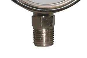
Stainless steel, straight BSP thread
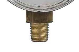
Copper alloy, tapered NPT thread
Flanged gauges are always equipped with a diaphragm seal. Also, for flanges, there is a large variety of types and diameters. Often ASME or DIN flanges are used in diameters ranging from 1/2″ to 4″ for ASME flanges and DN15 to DN100 for DIN flanges.
Clamped process connections come in many forms. A few examples include Tri-clamp, Varivent, Neumo BioControl … They are often used in the food and pharmaceutical industries for sanitary applications because they can be removed quickly for cleaning. They are always equipped with a diaphragm seal in order not to have dead zones capable of harboring bacteria.
Tip 7: Connection position
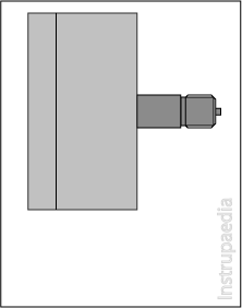
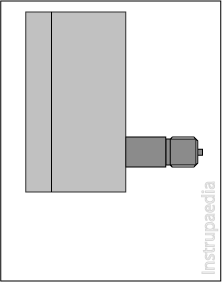
When choosing a pressure gauge you should always know in advance how the mounting will be carried out. Process connections may be at the bottom or back of the gauge. For measurements of pipe pressures, the connection will usually be at the bottom for mounting on the branch pipe. Pressure gauges mounted on pneumatic control equipment or panels usually have a rear connection.
Radial connection
Back connection
Offset-back connection
Tip 8: With or without a diaphragm seal
A diaphragm isolates the sensing element from the process medium and is normally used when the process conditions meet one or several of the following properties:
The medium is highly viscous.
The medium may crystallize or freeze.
The medium contains solids that will leave deposits.
The medium is corrosive and can damage the Bourdon tube.
The medium is toxic or dangerous. A diaphragm can provide additional protection against the pollution of the environment.
The temperature of the medium is outside the temperature range of the sensing element.
The occurrence of high overpressure. Use a diaphragm seal with a pre-formed membrane bed so that, when high pressure occurs, the membrane is pressed against the bed and does not deform.
Remote reading is necessary. This can be realized by making use of a capillary.
Sanitary cleanliness is required and dead spaces must be avoided. A flush-mounted diaphragm or an inline seal can be used for this purpose.
A diaphragm prevents the medium from entering the Bourdon tube and solidifying inside of it. If this happens, the last part of the Bourdon tube will no longer sense a change in process pressure causing the deflection of the pointer to be incorrect. Freezing of the medium in the Bourdon tube can cause structural damage to the sensing element.
Tip 9: Vibrations and mechanical shocks
Parts of a plant may be subject to vibration. If in these places the pressure has to be measured, the Bourdon tube will, because of its large overhang, vibrate to the rhythm of the machinery. Although it is better not to install a pressure gauge in these places, it is sometimes impossible to avoid it.
Mild vibrations give rise to small amplitude oscillations of the pointer which can be absorbed by filling the case of a pressure gauge with a liquid. The liquid which is most commonly used for this purpose is glycerin. This ensures damping of the vibrations of the Bourdon tube so that a proper reading is possible.
The liquid filling has the additional advantage of keeping moisture and humidity away from the internal components of the pressure gauge so the risk of corrosion is completely eliminated.
For vibrations of a higher magnitude or mechanical shocks, the fluid filling will not be enough. In this case, the pressure gauge must be installed at a distance, and the connection to the point of measurement will be done by means of a capillary tube and a diaphragm seal.
Tip 10: Pulsating pressure
Fluctuations of the pressure to be measured often give rise to large-amplitude oscillations of the pointer. This frequently occurs when a pressure gauge is mounted on a pump. These fluctuations can best be absorbed by mounting a snubber or a needle valve at the input of the pressure gauge. Both provide an adjustable restriction in the line causing pressure fluctuations to be damped. The result of this attenuation is an indication of the average value of the pulsating pressure.
Snubber
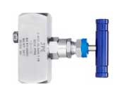
Needle valve
Tip 11: Overpressure
Any pressure above the maximum measuring range means overpressure on the pressure gauge. This gives rise to additional stress in the sensing element and will greatly reduce the service life and the accuracy of the pressure gauge.
To prevent this, you can choose a pressure gauge with a measuring range that is larger than the maximum operating pressure of the installation. This makes that overpressure on the system will be better absorbed by the pressure gauge.
Pressure peaks of a short duration can be countered by mounting a snubber or a needle valve between the pressure gauge and the measuring point.
To safeguard the gauge from long-term overpressures, overpressure protection can be installed between the gauge and the measuring point. If the pressure exceeds the set pressure of the overpressure protection, the pressure gauge will be isolated from the process. This is similar to closing a valve.
Tip 12: Fluid temperature
At temperatures above or below the temperature range of the pressure gauge, the accuracy will strongly decrease, and the possibility of gauge failure may exist. A dry pressure gauge can withstand higher process temperatures than a liquid-filled one. Several methods can be used to protect the pressure gauge against too cold or too hot temperatures.
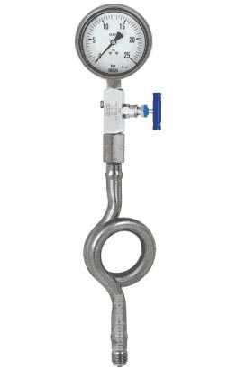
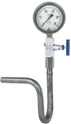
If steam is the process medium, a siphon can be used which is filled with water as in the pictures below.
Pigtail siphon
U-shape siphon
Due to the pressure of the steam, the water is pushed into the Bourdon tube so that it does not operate outside of its temperature range. By condensation of the steam in contact with the water, the siphon will never get empty. Do not forget to fill the siphon with the water before installing it.
A siphon cannot be used when the process medium is hot gas. With a vertical mounting of the pressure gauge, the gas, which is lighter than water, would rise through the water in the siphon. The Bourdon tube would be filled with gas at the same pressure as the process. Initially, the measurement would function but when the process pressure would decrease, the trapped gas in the Bourdon tube would expand and push out the water in the siphon. Over time, the siphon would be empty and the hot gas will penetrate into the Bourdon tube with the failure of the pressure gauge as a result.
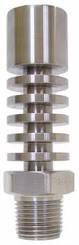
Another method to protect the pressure gauge against too high or too low temperatures is the use of a cooling element. For process temperatures above 150 °C (300 °F), it is recommended to use a cooling element combined with a diaphragm seal, and silicone oil filling. The cooling element is mounted between the separation membrane and the pressure gauge and filled with silicone oil. The ambient air flows along the fins of the cooling element and cools or heats the silicon filling oil. This allows a temperature reduction of 93 °C (200 °F) or more, depending on the ambient temperature and the length of the cooling element.
Cooling element
Yet another method is the use of a capillary. Capillaries protect gauges against too high or too low process temperatures. They are always used together with a diaphragm seal. The space behind the diaphragm, including the hollow tube of the capillary, and the Bourdon tube is filled with a liquid. This liquid passes the process pressure unabated to the pressure gauge. The fill fluid should be properly chosen in function of the process temperature.
Capillaries should be as short as possible since temperature changes have an impact on the fluid in the capillary. It’s affecting the accuracy and response time of the pressure gauge.
An additional advantage of capillaries is the possibility to mount the pressure gauge at a distance for remote reading.
If the temperature of a cold process medium falls just outside the temperature range of the pressure gauge, it can be enough to have a slightly longer than normal branch pipe to warm up the process media. The cold medium stands still in the narrow branch pipe and will warm up through heat exchange with the ambient air. Additional heating can be obtained by steam tracing or electrical tracing.
Tip 13: Ambient temperature
The normal ambient temperature range of a pressure gauge is situated between -40 °C and +60 °C (-40 °F and +140 °F) for dry pressure gauges and between -20 °C and +60 °C (-4 °F and +140 °F) for pressure gauges filled with glycerine.
For higher or lower temperatures, pressure gauges should be selected that are resistant to this temperature or the pressure gauge is to be installed at a distance, at a location where the ambient temperature is within the range of the pressure gauge. The pressure gauge is then connected to the measuring point through a capillary tube and a diaphragm seal.
Fluctuations in the ambient temperature do have an influence on the accuracy of the pressure gauge. A temperature change of the pressure gauge of +/- 8 °C (18 °F) rise or fall, gives a measurement error of +0.3% or -0.3% of the measuring range respectively. The reference ambient temperature is 20 °C (70 °F).
According to the EN 837-1 standard, the maximum allowed error of measurement, caused by the temperature effect, will be calculated as follows:
+/- 0,04 x (t2 – t1) % of the span for Bourdon tube pressure gauges
+/- 0,06 x (t2 – t1) % of the span for capsule pressure gauges
+/- 0,08 x (t2 – t1) % of the span for diaphragm pressure gauges
where:
t1 is the reference temperature in degrees Celsius
t2 is the ambient temperature in degrees Celsius
Tip 14: Safety aspect
If a Bourdon tube pressure gauge has been chosen for the application, also the safety design of the gauge should be taken care of. There are four categories to choose from:
0
Pressure gauge without blow-out device
S1
Pressure gauge with blow-out device
S2
Safety pattern pressure gauge without baffle wall
S3
Safety pattern pressure gauge with baffle wall
The choice of category is made in function of the measuring range, the nominal size of the pressure gauge, the process medium, and whether the case is liquid-filled or not.
An easy configurable Excel template is available for specifying pressure gauges. With this pressure gauge datasheet, Bourdon tube pressure gauges, diaphragm pressure gauges, bellows pressure gauges, and capsule pressure gauges can be defined.
Datasheet templates for other types of instruments can be found in the datasheet library.
“How do you select a pressure gauge?”
“Let us know what are the most important selection parameters for your application.”
Bellows are thin-walled metallic cylinders, with deep convolutions, of which one end is sealed and the other end remains open. The closed-end can move freely while the open-end is fixed.
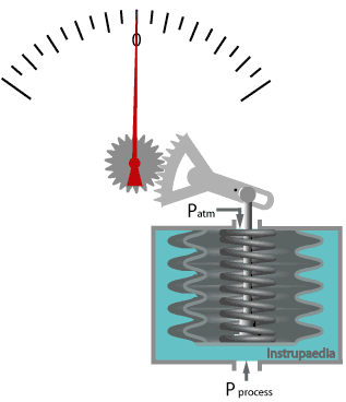
When pressure is applied to the closed-end, such as in the animation below, the bellows will be compressed. The closed-end will move upwards and the link, which is the rod in between the closed-end of the bellows and the transmission mechanism, will go up and rotate the pointer.
Compared with diaphragm and capsule pressure gauges, bellows gauges have the advantage of a longer stroke length and they generate larger forces.
The number of convolutions can vary between 5 and 20. More convolutions mean a longer stroke length and a larger measuring range.
The diameter of the bellows determines the force that can be transmitted to the transmission mechanism. Therefore a larger diameter will be chosen for the measurement of very low pressures in order to have sufficient surface area to which the measured pressure can act.
A larger diameter also means higher sensitivity and improved accuracy.
Bellows may be fabricated from different materials. Each of these materials has its own specific stiffness, which is proportional to Young’s modulus of the material and is inversely proportional to the outside diameter and the number of convolutions of the bellows.
The relationship between the pressure exerted on the bellows, and its deflection is linear and is only disrupted when the elastic limit is reached.
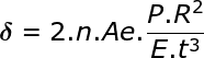
The deflection can be expressed as follows:
Where:
δ
=
deflection of the bellows
n
=
number of convolutions
Ae
=
effective surface of the bellows
P
=
pressure
R
=
average radius of the bellows
E
=
Young’s modulus
t
=
wall thickness
Bellows are sensitive to temperature changes, work hardening, drift, friction, hysteresis, and vibrations.
To compensate for these drawbacks, a bellows is generally used in combination with a calibrated spring.
As an additional advantage, the measuring range can be determined by the choice of the spring. Choosing a strong spring will lead to a large measuring range which makes it possible to measure large pressures with a bellows pressure gauge. For this reason, most bellows gauges are spring-loaded.
The spring also protects the bellows from being completely retracted or stretched beyond the elastic limit and thus extends its lifespan.
Measuring range of bellows pressure gauges
The pressure range is determined mainly by the effective area of the bellows and the spring gradient, and to a lesser extent by the material from which the bellows are made. For higher measuring ranges bellows will be used with a smaller diameter.
This kind of pressure gauges can be used to measure different types of pressure but are generally used for the measurement of low pressures, ranging from vacuum to about 3.5 barg.
Differential pressure gauges consisting of 2 opposing bellows with internal heavy range springs can be used at much higher static pressures (up to 750 barg) with a differential pressure measurement range of 69 bar.
Fabrication of bellows
Bellows are usually made from thin-walled seamless tubes pressed hydraulically, or mechanically roll formed.
Wall thicknesses of 0.008 to 0.3 mm are used for instrumentation purposes.
They can be manufactured from beryllium copper, phosphor bronze, Monel, Inconel, and stainless steel.
The bellows will have good hysteresis properties when using phosphor bronze, while beryllium copper provides better dynamic properties. Stainless steel is used when the bellows come into contact with corrosive media, but it has the disadvantage of being less elastic.
Relative pressure sensors
Bellows may be used both in compression and expansion.
When relatively low pressures are to be measured, the bellows will usually be used in expansion. The process pressure is then introduced to the inside of the bellows and causes the bellows to extend.
If more significant pressures are to be measured, it is better if the process pressure acts on the outside of the bellows. In this case, the bellows are compressed.
When measuring larger pressures, the bellows are always equipped with a heavy range spring.
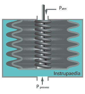
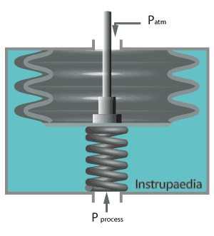
In both illustrations, below, the inside of the bellows is at atmospheric pressure whereas the outer side is subject to the process pressure. Both bellows, therefore, work in compression. The only difference between the two is the position of the spring. It can be located either on the inside of the bellows or on the outside.
Such sensors may also be used for the measurement of differential pressure. The only thing required is to replace the atmospheric pressure inside the bellows with a second process pressure.
Bellows in compression with internal spring
Bellows in compression with external spring
Also, a compound pressure gauge can be made with a single bellows when the inside of the bellows is exposed to atmospheric pressure and the process pressure can vary between vacuum and positive pressure. If the pointer rotates to the left, underpressure is measured, to the right means overpressure.
Compound gauge with a single bellows
Absolute pressure sensors
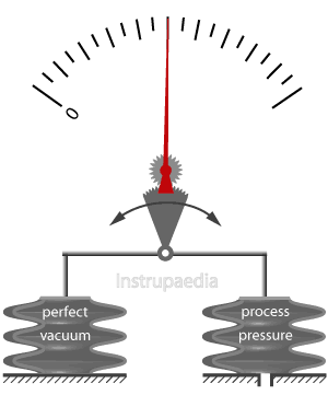
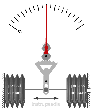
To measure absolute pressure we need two bellows. The first one is the reference bellows, which is provided with a perfect vacuum on the inside. The second one is the measuring bellows, which is subjected to the process pressure.
Since these absolute pressure sensors are generally used to measure low pressures, the bellows are not equipped with calibrated springs and they are used in expansion. The bellows will stretch with increasing process pressure.
The deflection of the bellows is transferred via the transmission mechanism to the pointer.
A change in the atmospheric pressure has no influence on the measurement in this case since the influence of this pressure on the two bellows is equally great.
Absolute pressure sensors exist in two different versions. On the one hand, there is the beam balance principle and on the other hand the opposed principle, as in the illustrations shown below.
Beam balance bellows principle
Opposed bellows principle
Differential pressure sensors
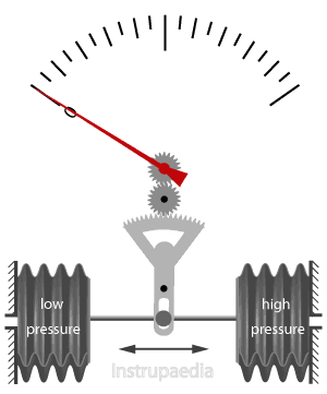
Just as differential pressure can be measured with a single bellows, as described above, we can also use dual bellows.
The low process pressure is connected to the first bellows while the high process pressure is connected to the second bellows.
Both of these process pressures will exert a force on the effective area of the bellows upon which they act. The resultant force rotates the pointer.
Differential pressure principle
These measurement devices can be designed for the measurement of differential pressures up to 70 bar or more, with an overpressure limit of up to 750 barg static pressure on both sides of the device.
At such high pressures, bellows with a small diameter are preferred, optionally provided with an internal or external spring. The accuracy will be less because of the need for a small diameter.
At high differential pressures, the accuracy is around 1.5% of the measuring range. At lower differential pressures up to 1 bar, accuracies of 0.5% of the measuring range are possible.
Datasheet template
An easy configurable Excel template is available for specifying bellows pressure gauges. This pressure gauge datasheet is designed to define bellows pressure gauges for all kinds of applications.
Datasheet templates for other types of instruments can be found in the datasheet library.
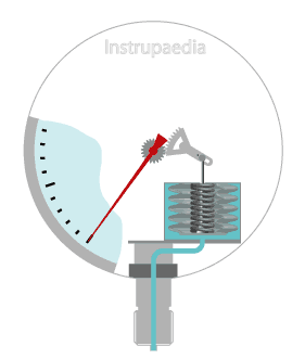
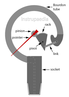
The Bourdon tube pressure gauge consists of a circular tube that is bent over an angle of generally 270°, and of which one end is closed and the other is connected to the process pressure.
The closed-end can move freely. This movement is transmitted via a transmission mechanism to the pointer of the pressure gauge, as you can see in the pressure gauge animation.
With the rack and pinion of the transmission mechanism, the movement of the Bourdon tube may be amplified so that the pointer rotates from start to end of the scale.
The Bourdon tube behaves like a spring that is deformed by the internal pressure in the tube.
To retain the pressure, the tube must have a certain wall thickness. Larger wall thicknesses are required for measuring higher pressures.
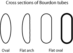
The wall thickness, the shape of the tube’s cross-section, the diameter of the C-shape, and the kind of material from which the tube is manufactured are determining factors for the elasticity of the Bourdon tube.
It is clear that a metal tube of sufficient thickness to hold the pressure is not enough elastic to create sufficient tip movement under the influence of small internal pressure. Bourdon tubes are, therefore, only used for measuring higher pressures.
In practice, this measuring principle can be found for measuring ranges between 0.6 bar (9 psi or 60 kPa) and 7000 bar (105,000 psi or 700,000 kPa).
The C-shaped tube is used for the lower measurement ranges up to about 60 bar (900 psi, or 6000 kPa). For higher measuring ranges spiral or helical Bourdon tubes are used.
A Bourdon tube is usually flattened on one or both sides. This allows the tube to lose some of its rigidity which makes it easier to uncoil when pressurized.
As the Bourdon tube has a circular form, the outer radius will be larger than the inner radius. The pressure in the Bourdon tube acts on a larger surface area along the outer radius and, consequently, will develop a larger force on that side so that the tube will straighten out.
The movement of the free end is non-linear as the same pressure increase at a Bourdon tube at rest has a greater effect on the displacement of the free end than when the tube has already been partially straightened. The reason for this is the resistance of the tube that increases when it becomes more straightened.
To be able to indicate the pressure on a linear scale, this nonlinearity must be compensated for by the transmission mechanism. Without compensation, the nonlinearity can reach up to 0.5% full scale. Cyclic pressures will cause an additional hysteresis of 0.2 to 0.5% of full scale.
In any case, this hysteresis may not be higher than the accuracy class of the pressure gauge.
The Bourdon tube is also sensitive to temperature changes. At low temperatures, the tube will be much stiffer and more difficult to straighten.
To keep this temperature effect as small as possible the construction material of the tube should be well chosen. Materials having a modulus of elasticity that is insensitive to temperature change are recommended.
Fast response time and good sensitivity are among the more desirable features of the Bourdon tube.
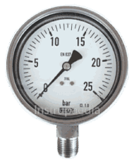
C-type Bourdon pressure gauge
The accuracy is situated between +/- 0.1 to +/- 5% of full scale and is determined by the Bourdon tube diameter, the wall thickness and the shape of the tube’s cross-section, the quality of the design, and the calibration. Incorrect installation or improper use can also cause a loss of accuracy.
Usually, a Bourdon tube pressure indicator is mounted vertically. Deviations of +/- 5° relative to the vertical position are permitted. A deviation of more than 5° will have an impact on accuracy.
When measuring the pressure of a liquid, the initially air-filled Bourdon tube will be filled up with liquid. As a result, air will be trapped by the liquid at the tube-end. This results in a sluggish performance of the pressure indication. A pressure gauge with a diaphragm and a liquid-filled Bourdon tube is a better choice in this case.
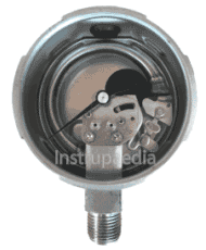
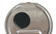
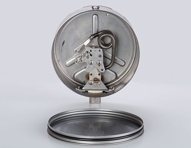
Interior view of a Bourdon gauge
The large overhanging free end of the Bourdon tube makes this measuring principle sensitive to vibrations.
When vibrations occur, the overhanging part will make small up and down movements. The transmission mechanism ensures that this movement is amplified and passed on to the pointer. As a result, the pointer will constantly move back and forth, making accurate reading impossible.
By immersing the Bourdon tube in a fluid (filling of the casing), the motion of the pointer can be damped. Glycerine is often used for this purpose. The liquid may be added through an opening on top of the casing which is then closed with a rubber plug. The filling continues until the Bourdon tube is fully submerged.
The fill fluid also prevents humidity from entering the enclosure. Fluctuations of the ambient temperature will otherwise create a kind of “breathing effect” inside the enclosure. Humid ambient air comes in, mostly at night, when temperatures are falling. With rising temperatures, air goes out again. When the dew point is reached, this humidity will condense causing corrosion of internal components and interior condensation on the window. All of this can be avoided by filling up the enclosure with glycerine.
Fill opening for liquid filling
Cyclic pressures have the same effect on the pointer as vibration.
The best way to get a stable readout is to use a snubber at the inlet of the pressure gauge. The fluid supplied to, or discharged from the Bourdon tube will be slowed down by the snubber and the pendulum movement of the pointer will be smaller and slower.
Filling the casing with glycerine may also help to dampen the pendulum motion of the pointer.
The frequent back and forth movement of the pointer will have an adverse effect on the wear of the rack and pinion. Backlash will occur at the gear teeth, thereby reducing the accuracy of the pressure gauge. Sometimes a hairspring is used, which is mounted on the shaft of the pointer, in order to ensure the necessary tension on the pinion so that the gears mesh properly.
Bourdon tube pressure gauges can be executed according to a safety design to protect the operator from high-pressure liquid or gas projections through the window of the pressure gauge in case the Bourdon tube should rupture.
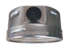
We distinguish the design types S1, S2, and S3. For the S1 type, the housing of the pressure gauge is equipped with a blow-out device (black plastic plug in the picture below).
Blow-out device
Gas or liquid being released is evacuated to a safe area away from the operator.
The window of the pressure gauge may additionally be made of safety glass. The blow-out device is activated at a pressure that is lower than half of the window-burst pressure.
Safety pattern gauges are of the S2 or S3 type and ensure even higher protection of the operator from a fatal rupture of the Bourdon tube.
Pressure gauges with a diameter between 40 and 80 mm, without an internal baffle wall, are of the S2 type and have a blow-out back. The blow-out back is usually the entire back of the pressure gauge and is blown away when the enclosure is being pressurized. The pressure in the enclosure is allowed to rise to a maximum of half of the pressure that is needed to break the window.
Pressure gauges with a diameter between 40 and 250 mm with an internal baffle wall are of the S3 type and also have a blow-out back. A baffle wall is a solid plate that is located between the Bourdon tube and the window. Upon failure of the Bourdon tube, the baffle wall will protect the window from being pressurized and the build-up pressure will blow away the blow-out back.
Both the S2 type and the S3 type are having windows made of safety glass.
Bourdon tube pressure gauges are fabricated according to certain standards. There are, among others, the European standard EN 837-1 and the US ASME B40.100. These standards provide terminology and definitions, dimensions, safety, construction and installation issues, test procedures, and general recommendations.
This video of the Australian company Floyd Instruments shows how pressure gauges are manufactured and uses beautiful graphics to further illustrate the functioning of the Bourdon tube pressure gauge.
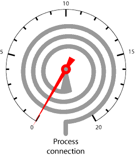
The spiral Bourdon tube makes a few windings in one plane around the fixed shaft of the pointer.
When the tube is being uncoiled by the process pressure, the free end will have a larger displacement compared to the C-shaped tube. The more windings, the larger the displacement will be.
A transmission mechanism is therefore no longer necessary. When the number of windings is correctly determined for a selected measuring range, a fixed connection between the free end of the Bourdon tube and the pointer is sufficient for a full deflection on the scale.
Using a fixed link avoids transmission losses due to friction or backlash in the transmission mechanism. This increases the accuracy and sensitivity of the pressure gauge. Also, recalibration is no longer necessary.
Backlash is mainly caused by wear on the teeth of the gears. Vibrations and pulsations are making it even worse. A pressure gauge with backlash on the gears will always indicate a pressure that is too low or too high. Subjected to pulsations, the backlash will cause the pointer to rotate further in both directions than would normally be the case without backlash. Having a fixed link is making the spiral Bourdon tube pressure gauge very resistant to extreme vibration or pulsation.
For low-pressure ranges, the spiral is made of a flat oval tube, while a round tube is being used for the high-pressure ranges.
The same low pressures can be measured with the spiral Bourdon tube as with the C-shaped Bourdon tube but the cost for a spiral pressure gauge is higher.
The use of spiral Bourdon tubes is consequently more likely in the high-pressure ranges which cannot be measured with the C-shaped tube because the wall thickness of the tube would be too large so that the tip movement is too small to have sufficient accuracy.
A clear representation of the operation of a spiral Bourdon tube is shown in this video from the company WIKA Instrument LP.
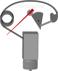
The helical Bourdon tube has several turns winded into a helix. The number of coils can vary from two or three to as many as twenty. They can be equipped with or without a transmission mechanism.
With 2 to 3 windings, as shown in the picture, the measuring range will rather be small and a transmission mechanism will be necessary to amplify the movement of the free end.
Having 16 to 20 windings, a larger measuring range becomes possible without the need for a transmission mechanism because the movement of the free end is large enough on itself.
When using a transmission mechanism, less movement of the free end is required which leads to less stress in the Bourdon tube. The fatigue life is thereby improved when compared to a C-shaped Bourdon tube.
The measurement range, however, is not only determined by the number of windings but also by the diameter, the wall thickness, and the type of material from which the Bourdon tube is manufactured.
Having more windings also increases the total volume of the Bourdon tube. This internal volume acts as a buffer for fluctuations in the process pressure. In this way, fluctuations are better absorbed, and the pointer will remain stable.
Due to the helically shaped design, this type is more robust than the spiral type. As a consequence this design is primarily used for large measurement ranges up to 7000 bar (105,000 psi or 700,000 kPa). On top of that, larger overpressures are permissible.
The accuracy of this type of gauge is normally found around +/- 1%.
Datasheet template
An easy configurable Excel template is available for specifying Bourdon tube gauges. With this pressure gauge datasheet, all three types of Bourdon tube pressure gauges discussed above can be defined.
Datasheet templates for other types of instruments can be found in the datasheet library.
The working principle of pitot tubes for measurement of volumetric flow
In this post, we will take a closer look at the pitot tube flow meter. We will discuss the different pitot tube types and look for the underlying principles that ensure that the pitot tube does what it should do, that is to measure the flow velocity.
But let’s start from the beginning.
What is a pitot tube?
A pitot tube, named after the French engineer Henri Pitot, is the sensing element of a differential pressure measurement that is used to measure the flow velocity of liquids and gases, including steam.
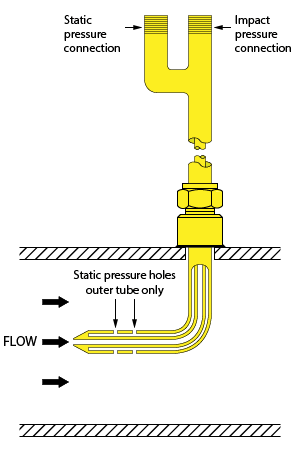
Classical designs have an L-shaped double-walled tube with the open end facing upstream and eventually one or more holes in the outer tube wall behind the open end. The inner and outer tube walls are connected to each other at the front hole, while at the other end both tubes are available for connection to a differential pressure instrument.
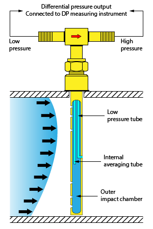
More recent designs are made of a straight multi-chamber tube, perpendicular to the flow direction, with multiple holes in the front and the rear chamber of the tube. Both chambers come out separately at the top of the pitot tube for connection to the pressure instrument.
Original L-shaped pitot tube
More recent averaging pitot tube
The DP signal from the pitot tube can be measured by a differential pressure transmitter which then converts the signal to a flow velocity provided that the density of the fluid is known. By combining a pitot tube and a differential pressure transmitter, we get a pitot tube flow meter.
When the pitot tube is installed in a conduit with a known cross-sectional area, it becomes possible to calculate the volumetric flow by multiplying the measured flow velocity by the cross-sectional area.
Further multiplication of the volume flow by the density of the fluid gives us the mass flow rate.
The pitot tube flow meter working principle
Pitot tube flow meter animation
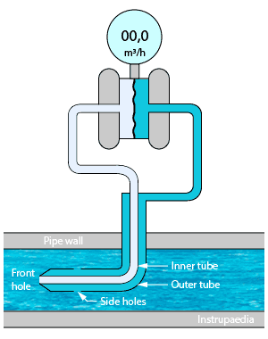
The drawing above is showing a classical pitot tube inserted into a conduit with the tube opening oriented against the flow.
If the fluid is not flowing, the pressure will be the same in the inner and outer tubes. This pressure is called static pressure.
As soon as the fluid starts to flow, a part of the fluid will enter the pitot tube through its front hole, but it has nowhere to go because the inner tube is closed at the back as it is connected to the pressure transmitter. So, once the tube has filled up, the fluid will come to a standstill (stagnation) inside the tube.
However, the fluid continues to flow through the conduit and the molecules build up kinetic energy. Because the fluid can no longer enter the pitot inner tube, all molecules will collide at the front hole. This brings them to a full stop and they lose their kinetic energy.
But energy is never lost. So, with every collision, the kinetic energy is converted into pressure energy.
The pressure built up at the tip of the pitot tube is called the stagnation pressure, sometimes also called the total pressure. It is the sum of the static pressure, equally distributed in all directions, and the dynamic pressure, caused by the conversion of the kinetic energy and effective in the flow direction only.
A number of small holes were drilled in the outer tube. Since these openings are perpendicular to the direction of flow, they are not influenced by the dynamic pressure. They are only subjected to static pressure.
We could say that the inner tube is sensing the stagnation pressure, while the outer tube is sensing the static pressure.
A pitot tube that measures both the stagnation and the static pressure is called a pitot-static tube or Prandtl tube. If the two tubes coming out of the pitot-static tube are connected to a differential pressure transmitter, as shown in de animation above, we can measure the dynamic pressure of the fluid flow.
Dynamic pressure = ΔP = Pstagnation – Pstatic
We will need the result of this measurement to calculate the flow velocity of the fluid.
To find the formula for the calculation of the flow velocity, we have to start from the basic principle, the Bernoulli equation:
P1 +
12ρV12 =
P2 +
12ρV22
Those who are not familiar with this formula should read the article about the Bernoulli principle first, as that will explain how we arrive at this formula.
In the above equation, the potential energy terms (ρgh) have already been canceled because we are assuming a horizontal flow.
The velocity V2 at the front hole of the pitot tube is stagnated. This means that V2 is equal to zero, and we can delete the full term
12ρV22.
This simplifies the equation to:
P2 – P1 = ΔP =
12ρV12
Solving for V1 gives us the flow velocity in the conduit:
V1 =
√2ΔPρ
Where:
V1
=
velocity of the fluid
ΔP
=
the measurement value of the pressure transmitter
ρ
=
density of the fluid
With the velocity of the fluid now known, we can obtain the volumetric flow rate by multiplying the velocity by the cross-sectional area of the conduit.
Qv =
A1V1 =
Π4D2√2ΔPρ
Where:
Qv
=
volumetric flow rate
A1
=
cross-sectional area
D
=
diameter of the conduit
Even the mass flow rate can now be calculated if we multiply the volumetric flow rate by the density of the fluid.
Qm =
ρQv =
ρΠ4D2√2ΔPρ
Where:
Qm
=
mass flow rate
Or, if you don’t want a fraction under the square root:
Qm =
Π4D2√2ΔPρ
The density of the fluid can be obtained as follows:
When the pressure and the temperature of the fluid are constant, the density can be found in a density table for that specific fluid. That value can then be programmed into the control system.
When the temperature and the pressure change continuously, these need to be measured and their measured value sent to the control system. The density table for that specific fluid must then be programmed into the control system so that the system can select the density value that corresponds to the pressure and temperature it has received.
It has to be said that to arrive at these formulas, we had to make the following assumptions:
The fluid we are measuring is incompressible
There are no dissipative forces (heat loss, friction)
The fluid is non-viscous
The flow is steady laminar
Different types of pitot tubes
L-type pitot tube
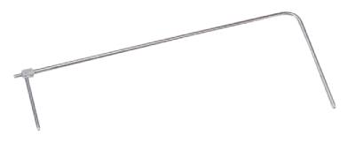
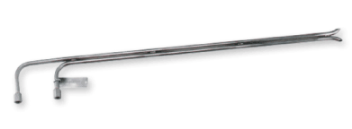
This is a basic pitot-static tube like the one I used for the animation above. It has the typical L-shape consisting of the head, which has to be aligned with the fluid flow, and the stem which passes through the wall of a conduit. The length of the head is generally between 15 and 25 times the head diameter.
The tip of the head has a front hole that is connected to a smaller tube that runs inside the head and stem and comes out the other side parallel to the stem. This inner tube transfers the total pressure registered by the front hole.
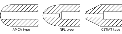
The tip of the L-type pitot tube can be designed in 3 different ways:
a spherical shaped tip (AMCA type)
an ellipsoidal shaped tip (NPL type)
a conical shaped tip (CETIAT type)
Different tip shapes of the L-type pitot tube
Eight static pressure holes are drilled around the circumference of the head at a distance of 6 to 8 times the head diameter from the tip. The static pressure is transferred through the outer tube and comes out at a branch perpendicular to the stem. This branch also serves as an alignment arm to facilitate head alignment since the visibility of the head is obstructed by the conduit wall.
A standard pitot tube provides acceptable gas velocity measurements as long as the tube direction does not deviate more than 15° from the flow direction. When the deviation exceeds 15°, the dynamic pressure reading decreases rapidly.
S-type pitot tube
The probe is inserted into the conduit with its total pressure hole upstream, facing the flow, and its static pressure hole downstream pointing in the direction of the flow. The faces of both openings must be perpendicular to the flow.
The large openings of typically 4 – 10 mm permit the S-type probe to be used in gases containing dust or fine droplets. The large holes are not easily plugged and therefore these types of pitot tubes are often used for flow measurement in emission stacks.
Because the total pressure hole is obstructing the flow to the static pressure hole and given the size of these holes, the flow profile at the static pressure hole will be disturbed.
As a result :
The measured static pressure will be lower than the real static pressure. To compensate for this difference, the S-type pitot tube must be calibrated.
The measured differential pressure will be higher compared to the L-type pitot tube, which is beneficial in low-velocity gas flow applications.
Just like the L-type pitot tube, the S-pitot tube provides an acceptable measurement when the direction of the gas flow does not deviate more than 15° from the direction of the pitot tube.
Rotating the S-tube by 90°, so it stands perpendicular to the flow direction, leads to a measured differential pressure that equals zero.
This makes it possible to determine the flow direction of the gas and the tangential flow angle, by rotating the S-pitot tube until the measured differential pressure is zero.
The tangential flow angle is the angle between the flow direction of the gas and the axial direction of the conduit.
If the tangential flow angle is greater than 15°, then the velocity corrected for flow direction is given by:
vc =
cosθmeasvmeas
Where:
vc
=
velocity corrected for flow direction
cosθmeas
=
cosine of the tangential flow angle
vmeas
=
velocity measured at angle θmeas
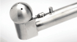
3D pitot tube
A 3D pitot tube
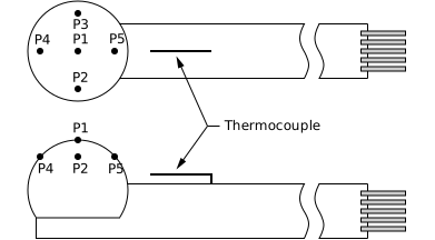
Top and side view of a 3D pitot tube
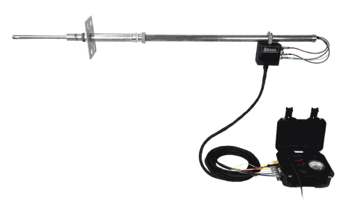
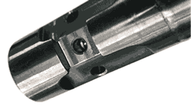
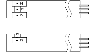
This type of probe consists of 5 pressure taps in a spherical (or prism-shaped) sensor head. The pressure taps are numbered P1 to P5 in a fixed sequence.
Inside the pitot probe are five separate tubes connecting each pressure tap with the measuring device for evaluation of the measured pressure.
The temperature of the gas is measured by a thermocouple on the stem of the probe.
A 3D-probe is used in a particular case when stack gas has a flow profile with a significant yaw angle and pitch angle. In this case, the L- or S-probes would lose too much of their accuracy to perform a reliable measurement.
The 3D-probe can determine the yaw and pitch angle and the dynamic pressure by using its 5 pressure taps.
To find the yaw angle the probe is rotated around its axis until the differential pressure P2 – P3 equals zero. This operation is called yaw nulling. An inclinometer will then calculate the yaw angle and its value will be displayed on the console.
The differential pressure P4 – P5 is used to calculate the pitch angle using probe-specific calibration curves.
The differential pressure P1 – P2 is a function of total velocity.
From these values and a determination of the gas density, the average axial velocity of the gas is calculated.
The average gas volumetric flow rate can be found by multiplying the average axial velocity by the cross-sectional area of the conduit.
2D pitot tube with inclinometer and console
2D pitot tube
A 2D pitot tube
Top and side view of a 2D pitot tube
The 2D probe may look the same as the 3D probe (both can be prism-shaped) but has only 3 pressure taps, numbered P1, P2, and P3, at the same spot as the 3D probe.
Therefore, the 2D probe can only measure the velocity pressure and the yaw angle.
P1 – P2 determines the velocity pressure
P2 – P3 is used to find the yaw angle
From these measurements and the density of the gas, the average near-axial velocity of the gas is calculated.
Notice that a 2D probe only measures the near-axial velocity, since it ignores the pitch component of the flow.
Multiplying the near-axial velocity by the cross-sectional area of the pipe gives the average gas volumetric flow rate.
It is also possible to use a 3D as a 2D probe by operating the 3D probe in the yaw determination mode only.
A datasheet or spec sheet is a document that specifies the technical characteristics of a piece of equipment. It is a summary of all properties of the equipment, the process data and environmental conditions of the location where the device will be installed, and the necessary certificates to comply with local legislation.
What’s the importance of an instrument datasheet?
An instrument datasheet is generated by an instrument engineer during the detailed engineering phase of a project. It is a document that contains plenty of information that may concern several other disciplines such as designers, automation engineers, purchasers, vendors, and maintenance technicians. The importance of an instrument datasheet lies in the fact that so many people use this information during the different design phases of a project and possibly also at a later stage for maintenance.
What follows is an overview of the different people who benefit from a well-prepared and detailed specification sheet.
Benefits for the mechanical designer
The mechanical or piping designer needs to draw the in-line instruments, such as valves or flow meters, on the piping drawing. Instruments that are not in-line are mounted on nozzles, flanged or threaded. To make these drawings, the piping designer needs the following information from the datasheet:
Face-to-face dimensions of all in-line instruments.
Size, class, and type of flanges or screw-threads for instruments mounted on nozzles.
The 3D-dimensions of the instruments so that enough space can be provided for the device.
The insertion length for each instrument that is inserted into the pipe.
Benefits for the instrument designer
The instrument or E&I designer needs to wire each instrument and should, therefore, receive the manufacturer’s wiring diagrams. He also needs to make the hook-up drawings to show how the instrument should be mounted and/or tubed. For this reason, he needs the following information from the datasheet:
Power supply and power consumption of the instrument.
The wiring system, two-wire or four-wire, for analog instruments. Four-wire systems are powered by an external source.
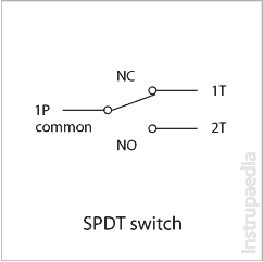
The contact arrangement of a switch for discrete instruments, e.g. SPST or SPDT.
The thread size and type of the in/out ports for tubed instruments.
The possible use of a manifold and/or a mounting bracket supplied by the vendor.
schematic representation of an SPDT switch
Benefits for the automation engineer
The automation engineer writes the program for the PLC or DCS and designs the user interface for the HMI screens. Various data from the datasheet can be useful to him, such as:
The calibrated range of the analog signals to configure the control system’s input channel.
The units of the measurements displayed on the HMI screen.
The type of bus and the protocol for communication between the instrument and the PLC or DCS.
Benefits for the purchaser
The purchaser is charged with the task to find the instrument on the market. His benefits from a datasheet are the following:
Since he is not so well versed in technical jargon, it is easier to just refer to the datasheet.
Sending an instrument specification datasheet to multiple vendors creates competition between them and this will provide him with the best price or the best value for money.
Benefits for the vendor
The vendor chooses the appropriate instrument from his catalog and sends a quotation to the purchaser. All he needs is:
To receive a concise and well-arranged document that makes it quickly clear what the customer wants.
Every vendor to receive the same information to be on equal footing with his competitors. This ensures fair competition.
Benefits for the maintenance technician
The service technician must maintain the device. This means that the device must be regularly calibrated or replaced by another device in the event of an irreparable defect. He can use the datasheet:
To find the calibrated range and the measurement units.
To purchase a new instrument in case of a total loss of the installed device.
And last but not least:
Benefits for the instrument engineer
Using a datasheet for purchasing an instrument or a piece of equipment has a number of advantages for the instrument engineer as well:
Completing the datasheet makes you think about what is needed for your application. It should be a process that leads to only listing the minimum requirements for a device. Specifying too much may cost you more money.
Using a generic datasheet template made for this kind of equipment makes it almost impossible to overlook something. With all possible property descriptions already mentioned on the datasheet template, you just have to go through them one by one and enter what you need next to each property description.
A datasheet will give you a clear overview of your application needs and all of the properties and technical specifications of the equipment.
By asking the supplier to complete the datasheet, it becomes possible to easily compare equipment proposed by different suppliers.
Which devices justify the use of a datasheet for purchasing?
In general, you could say that any instrument with a large set of parameters to be specified needs a datasheet to purchase it and that simple instruments with only a few parameters could do without a datasheet.
In practice, however, all instruments, from simple gauges to complex analyzers, have a large set of parameters. Think about the many process parameters, the materials of construction, process connections, power requirements, measurement range, output signals, setpoint(s), area classification… Enough information to fill one or more pages of a datasheet.
Because of the complexity of an instrument, I would recommend to always use a datasheet for the purchase of a device.
The lifespan of a datasheet
The datasheet will prove valuable as long as the purchasing process is ongoing. You can make use of it during the evaluation of tenders so you can easily check whether the supplier is offering the right material. When you have finally made your choice, you can send the datasheet as an attachment to the order.
Once the material has been delivered, you probably won’t need the datasheet any longer except if you want to buy a similar instrument later on.
Some companies are using the datasheets for maintenance. In this case, they will need to keep the datasheet updated every time the calibrated range has been changed or the instrument has been replaced by another one.
Instrument datasheet templates
Drawing up a comprehensive datasheet is time-consuming. You will have to make sure you do not forget to mention any attributes, that you provide sufficient space for the supplier to fill in something, and last but not least, you must use the correct technical terms, otherwise, misunderstandings will occur.
You can do all that by yourself and spent some hours behind your computer, or you could just take a look at this collection of datasheet templates and see if you can use one of them. There are datasheet templates for pressure gauges, pressure transmitters, pressure switches, thermometers, RTD temperature transmitters, level transmitters, … and many more will be available in the future.
“Do you know of any other benefits for using datasheets?”
“We love to hear what you think about it, so don’t hesitate to write down your thoughts in the comments below.”
Select the unit you want to convert from in the input unit list on the left.
Select the unit you want to convert to in the output unit list on the right.
Enter the value of the input unit to convert from in the input box on the left.
The tool will immediately display the equivalent value of the output unit in the output box on the right.
Steps 1 to 3 may be executed in random order.
The value of your input unit can be converted to any other unit by just selecting a different output unit in the list on the right.
Definition of flow rate
Flow rate (Q) is defined to be the volume (V) of fluid passing through a cross-sectional area (A) during a period of time (t).
With a formula, this can be written as:
Q =
Vt
The basic unit for flow rate in the metric system is m3/s (SI unit).
However, this is a very large unit, causing the quantity for small flow rates to be a very small number starting with a zero and followed by multiple zeros after the decimal point. Since this is not practical, often use is made of derived units of the SI system. These are, for example, m3/h, and l/h or l/min.
How to calculate flow rate?
Let’s take the example of a liquid flowing through a uniform pipe with a cross-sectional area A.
The liquid is flowing from left to right through the pipe.
Time t0 is the point where we start the measurement and time t1 is the endpoint of the measurement.
During the time interval t1 – t0, a certain volume of liquid has passed through the cross sectional area A. This volume can be calculated as follows:
V = A x d
where d = the distance travelled by the liquid during time interval t1 – t0
The flow rate through the pipe will then be:
Q =
Vt =
A x dt1 – t0
The average flow velocity through the pipe is:
vav =
dt1 – t0
So, if you only know the cross-sectional area and the speed at which the liquid is moving through the pipe, you can use an alternative formula to calculate the flow rate:
Q = A x vav
Interpretation of flow rate units
A flow can be considered as fluid in motion, moving from one place to another in a steady stream.
The descriptions of some units below are written in such a way that you can get an idea of what this unit means. Other, similar units can easily be derived from this description by simply replacing a few words in the sentence (e.g., hour replaced by minute or yard replaced by foot).
Cubic meter per second – The quantity of liquid equivalent to a flow, one meter wide by one meter deep, flowing with a velocity of one meter per second.
Liter per hour – The amount of liquid equivalent to a flow that fills a volume of one liter every hour.
Gallon per hour – The amount of liquid equivalent to a flow that fills one gallon every hour.
Acre-foot per hour – The volume of liquid, covering one acre one foot deep, which moves from one place to another in one hour.
Cubic yard per hour – The quantity of liquid equivalent to a flow, one yard wide by one yard deep, flowing with a velocity of one yard per hour.
Conversion factors Imperial/Customary to Metric
The following tables are showing the conversion factors from the Imperial and US Customary system to the Metric system.
CONVERT TO (multiply by)
CONVERT FROM
m3/s
m3/min
m3/h
cm3/s
cm3/min
cm3/h
L/s
L/min
L/h
gal(US)/s
0.003785
0.227124
13.62748
3785.41
227124.7
13627482.4
3.785412
227.1247
13627.48
gal(US)/min
0.000063
0.003785
0.227125
63.09019
3785.412
227124.7
0.063090
3.785412
227.1247
gal(US)/h
1.052×10⁻⁶
0.000063
0.003785
1.051503
63.09019
3785.412
0.001051
0.063090
3.785412
gal(UK)/s
0.004546
0.272765
16.36592
4546.09
272765.4
16365924
4.54609
272.7654
16365.92
gal(UK)/min
7.577×10⁻⁵
0.004546
0.272765
75.76817
4546.09
272765.4
0.075768
4.54609
272.7654
gal(UK)/h
1.263×10⁻⁶
7.577×10⁻⁵
0.004546
1.262803
75.76817
4546.09
0.001263
0.075768
4.54609
bbl(US)/s
0.158987
9.539238
572.3543
158987.3
9539237.7
572354261.7
158.9873
9539.238
572354.3
bbl(US)/min
0.002650
0.158987
9.539238
2649.788
158987.3
9539237.7
2.649788
158.9873
9539.238
bbl(US)/h
0.000044
0.002650
0,158987
44.16314
2649.788
158987.3
0.044163
2.649788
158.9873
bbl(US)/d
1.84×10⁻⁶
0.000110
0,006624
1.840131
110.4078
6624.471
0.001840
0.110408
6.624471
Some factors are slightly rounded compared to the factors used in the Flow Units Converter.
CONVERT TO (multiply by)
CONVERT FROM
m3/s
m3/min
m3/h
cm3/s
cm3/min
cm3/h
L/s
L/min
L/h
ac*ft/h
0.342635
20.55811
1233.487
342635.2
20558112.8
1233486771
342.6352
20558.11
1233486.7
hcf/min
0.047195
2.831685
169.9011
47194.74
2831684.6
169901079
47.19474
2831.685
169901.1
hcf/h
0.000786
0.047195
2.831685
786.5791
47194.74
2831684.6
0.786579
47.19474
2831.685
oz/s
2.9574×10⁻⁵
0.001774
0.106465
29.57353
1774.412
106464.7
0.029573
1.774412
106.4647
oz/min
4.93×10⁻⁷
2.9574×10⁻⁵
0.001774
0.492892
29.57353
1774.412
0.000493
0.029573
1.774412
oz/h
8×10⁻⁹
4.93×10⁻⁷
2.9574×10⁻⁵
0.008215
0.492892
29.57353
8.215×10⁻⁶
0.000493
0.029573
oz(UK)/s
2.8413×10⁻⁵
0.001705
0.102287
28.41306
1704.784
102287.0
0.028413
1.704784
102.2870
oz(UK)/min
4.74×10⁻⁷
2.8413×10⁻⁵
0.001705
0.473551
28.41306
1704.784
0.000474
0.028413
1.704784
oz(UK)/h
8×10⁻⁹
4.74×10⁻⁷
2.8413×10⁻⁵
0.007893
0.473551
28.41306
7.893×10⁻⁶
0.000474
0.028413
Some factors are slightly rounded compared to the factors used in the Flow Units Converter.
CONVERT TO (multiply by)
CONVERT FROM
m3/s
m3/min
m3/h
cm3/s
cm3/min
cm3/h
L/s
L/min
L/h
yd3/s
0.764555
45.87329
2752.397
764554.8
45873291
2752397489
764.5548
45873.29
2752397.5
yd3/min
0.012742
0.764555
45.87329
12742.58
764554.8
45873291
12.74258
764.5548
45873.29
yd3/h
0.000212
0.012742
0.764555
212.3763
12742.58
764554.8
0.212376
12.74258
764.5548
ft3/s
0.028317
1.699011
101.9406
28316.85
1699010.8
101940648
28.31685
1699.011
101940.6
ft3/min
0.000472
0.028317
1.699011
471.9474
28316.85
1699010.8
0.471947
28.31685
1699.011
ft3/h
7.866×10⁻⁶
0.000472
0.028317
7.865791
471.9474
28316.85
0.007866
0.471947
28.31685
in3/s
1.6387×10⁻⁵
0.000983
0.058993
16.38706
983.2238
58993.43
0.016387
0.983224
58.99343
in3/min
2.73×10⁻⁷
1.6387×10⁻⁵
0.000983
0.273118
16.38706
983.2238
0.000273
0.016387
0.983224
in3/h
5×10⁻⁹
2.73×10⁻⁷
1.6387×10⁻⁵
0.004552
0.273118
16.38706
4.552×10⁻⁶
0.000273
0.016387
Some factors are slightly rounded compared to the factors used in the Flow Units Converter.
Example of conversion
Conversion from US Customary gal(US)/s to Metric m3/s:
5 gal(US)/s = 5 x 0.003785 m3/s = 0.018925 m3/s
If you perform this conversion directly in the converter, you will see that the sixth digit after the decimal point is different. This is because the conversion factors in the tables are rounded. The converter is more accurate.
Conversion factors Metric to Imperial/Customary
The following table is showing the conversion factors from the Metric system to the Imperial and US Customary system.
CONVERT TO (multiply by)
CONVERT FROM
gal(US)/s
gal(US)/min
gal(US)/h
gal(UK)/s
gal(UK)/min
gal(UK)/h
bbl(US)/s
bbl(US)/min
bbl(US)/h
bbl(US)/d
ac*ft/h
hcf/min
hcf/h
oz/s
oz/min
oz/h
oz(UK)/s
oz(UK)/min
oz(UK)/h
yd3/s
yd3/min
yd3/h
ft3/s
ft3/min
ft3/h
in3/s
in3/min
in3/h
m3/s
264.1720
15850.32
951019.4
219.9692
13198.15
791889.3
6.289811
377.3886
22643.32
543439.6
2.918556
21.18880
1271.328
33814.023
2028841.4
121730482
35195.08
2111704.6
126702279
1.307951
78.47704
4708.622
35.31467
2118.880
127132.8
61023.74
3661424.6
219685479
m3/min
4.402867
264.1720
15850.32
3.666154
219.9692
13198.15
0.104830
6.289811
377.3886
9057.327
0.048642
0.353147
21.18880
563.5670
33814.02
2028841.4
586.5846
35195.08
2111704.6
0.021799
1.307951
78.47704
0.588578
35.31467
2118.880
1017.062
61023.74
3661424.6
m3/h
0.073381
4.402867
264.1720
0.061102
3.666154
219.9692
0.001747
0.104830
6.289811
150.9554
0.000811
0.005886
0.353147
9.392784
563.5670
33814.02
9.776410
586.5846
35195.08
0.000363
0.021799
1.307951
0.009810
0.588578
35.31467
16.95104
1017.062
61023.74
cm3/s
0.000264
0.015850
0.951020
0.000220
0.013198
0.791889
6.29×10⁻⁶
0.000377
0.022643
0.543440
2.919×10⁻⁶
2.1189×10⁻⁵
0.001271
0.033814
2.028841
121.7305
0.035195
2.111705
126.7023
1.308×10⁻⁶
7.8477×10⁻⁵
0.004709
3.5315×10⁻⁵
0.002119
0.127133
0.061024
3.661425
219.6855
cm3/min
4.403×10⁻⁶
0.000264
0.015850
3.666×10⁻⁶
0.000220
0.013198
1.05×10⁻⁷
6.29×10⁻⁶
0.000377
0.009057
4.9×10⁻⁸
3.53×10⁻⁷
2.1189×10⁻⁵
0.000563
0.033814
2.028841
0.000586
0.035195
2.111705
2.2×10⁻⁸
1.308×10⁻⁶
7.8477×10⁻⁵
5.89×10⁻⁷
3.5315×10⁻⁵
0.002119
0.001017
0.061024
3.661425
cm3/h
7.3×10⁻⁸
4.403×10⁻⁶
0.000264
6.1×10⁻⁸
3.666×10⁻⁶
0.000220
2×10⁻⁹
1.05×10⁻⁷
6.29×10⁻⁶
0.000151
8.1071×10⁻¹⁰
6×10⁻⁹
3.53×10⁻⁷
9.393×10⁻⁶
0.000563
0.033814
9.776×10⁻⁶
0.000586
0.035195
3.6332×10⁻¹⁰
2.2×10⁻⁸
1.308×10⁻⁶
1×10⁻⁸
5.89×10⁻⁷
3.5315×10⁻⁵
1.6951×10⁻⁵
0.001017
0.061024
L/s
0.264172
15.85032
951.0194
0.219969
13.19815
791.8893
0.006290
0.377389
22.64332
543.4396
0.002918
0.021189
1.271328
33.81402
2028.841
121730.5
35.19508
2111.705
126702.3
0.001308
0.078477
4.708622
0.035315
2.118880
127.1328
61.02374
3661.425
219685.5
L/min
0.004403
0.264172
15.85032
0.003666
0.219969
13.19815
0.000105
0.006290
0.377389
9.057327
4.8643×10⁻⁵
0.000353
0.021189
0.563567
33.81402
2028.841
0.586585
35.19508
2111.705
2.1799×10⁻⁵
0.001308
0.078477
0.000588
0.035315
2.118880
1.017062
61.02374
3661.425
L/h
7.3381×10⁻⁵
0.004403
0.264172
6.1103×10⁻⁵
0.003666
0.219969
1.747×10⁻⁶
0.000105
0.006290
0.150955
8.11×10⁻⁷
5.886×10⁻⁶
0.000353
0.009393
0.563567
33.81402
0.009776
0.586585
35.19508
3.63×10⁻⁷
2.1799×10⁻⁵
0.001308
9.81×10⁻⁶
0.000588
0.035315
0.016951
1.017062
61.02374
Some factors are slightly rounded compared to the factors used in the Flow Units Converter.
Example of conversion
Conversion from Metric m3/s to US Customary gal(US)/s:
3 m3/s = 3 x 264.1720 gal(US)/s = 792.516 gal(US)/s
Advertisement
Length units converter
Convert feet to meters, inch to cm, mm to m …
UnitConversion.org – the universal assistant for all of your unit conversion needs.
The meter is the length of the path traveled by light in vacuum during a time interval of 1/299 792 458 s.
The base unit of length is the meter. Multiples and submultiples are indicated by a system of prefixes, e.g. kilo-, hecto-, deka-, deci-, centi-, milli-… as can be seen in the table below. Please note that this table is not complete and doesn’t show all possible prefixes.
Examples of conversion:
1 kilometer = 1 x 10 = 10 hectometer
1 meter = 1 x 10 x 10 = 100 centimeter
25 millimeter = 25 x
110 x
110 x
110 = 0.025 meter
10000 decimeter = 10000 x
110 x
110 x
110 x
110 = 1 kilometer
Imperial and US customary length conversion
The US Customary system is similar to, but not to be confused with, the Imperial system still used in the United Kingdom. There are differences between the two systems, especially for units of volume and mass. But for length units, they are the same.
The units of length in the US Customary system have two slightly different definitions, leading to two different systems of measure: the International measure and the US Survey measure.
International measure
The international measure uses the same definition for the units of length as the imperial system. One inch international measure is exactly 25.4 millimeters.
The United States primarily uses International measure units in commercial activities, engineering, and for personal daily use.
Examples of conversion:
1 mile = 1 x 1760 = 1760 yard
1 yard = 1 x 3 x 12 = 36 inch
6.3 foot = 6.3 x
13 = 2.1 yard
63360 inch = 63360 x
112 x
13 x
11760 = 1 mile
US Survey measure
US Survey measure uses a different and older definition for the units of length whereby one inch is defined in such a way that 39.37 inches equal exactly 1 meter. The units of the US Survey measure are only used for surveying.
The difference between an international foot and a survey foot is very small. One international foot is exactly 0.999998 of a US survey foot. This makes it a difference of about
18 inch (3mm) per mile.
Examples of conversion:
1 league = 1 x 3 = 3 survey mile
1 furlong = 1 x 10 x 4 = 40 rod
660 survey foot = 660 x
116.5 x
14 x
110 = 1 furlong