Potentiometer – Questions & Answers
 11 March 2019
What is a potentiometer?
A potentiometer is an electrical component that is used as a voltage divider. It consists of:
- a resistive element with electrical terminals on both ends
- a wiper that can move along the resistance path and makes contact with it through sliding contacts
- a third electrical terminal connected to the wiper
- a housing that contains both the resistive element and the wiper
When a voltage is applied to the ends of the resistive element, a part of that voltage can be tapped by the wiper.
The position of the wiper on the resistance path determines the amount of tapped voltage.
How a potentiometer works
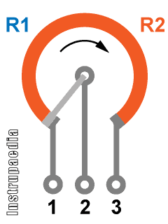
A potentiometer can be considered as two variable resistors in series, with the wiper connected in between the two resistors.
When the wiper is turned to the right, R1 becomes larger and R2 becomes smaller
Start the animation below to see how that works out.
Schematically, you can simply imagine a potentiometer as follows:

If you apply a voltage to pins 1 and 3, the potentiometer will make sure that voltage is divided over the resistors R1 and R2.
How much voltage will be across each of these resistors depends on their resistance.
When no load is connected to pins 1 and 2, Vout can be calculated with the formula:

The output voltage will be slightly different when a load would be connected because the resistance of the load RL and the resistance of R1 will then be in parallel. So, the output voltage would then be calculated with the following formula:

What are potentiometers used for?
The best-known application of potentiometers is for volume control of audio devices. Radios and old-style televisions use a potentiometer with a knob to increase or decrease the volume.
However, potentiometers can also be used to control the output frequency of a circuit, the rotational speed of a motor, or to balance or calibrate a circuit.
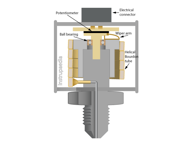
Because they are relatively cheap and relatively easy to manufacture, they are also often used as a sensor in measuring devices such as the potentiometric pressure transducer or the position feedback for on/off and control valves.
There are many more applications for potentiometers.
In general, we can say that they are used when something needs to be adjusted or controlled.
How to connect a potentiometer?
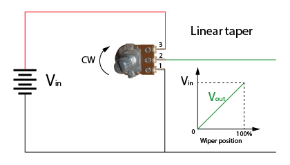
If you use it as a voltage divider, connect pin 1 to the ground and the positive potential of the source to pin 3. The wiper of the potentiometer is always connected to pin 2.
With the load wired between pin 1 and 2, the voltage over the load will increase when turning the potentiometer clockwise.
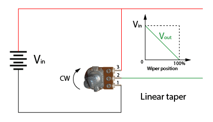
With the load wired between pins 2 and 3, the voltage over the load will decrease when turning the potentiometer clockwise.
There is a very nice WikiHow page about how to wire a potentiometer in case you need more information.
Can a potentiometer be used as a rheostat?
Yes and no, it all depends on how much power needs to be supplied.
A rheostat is nothing more than a variable resistor. Unlike a potentiometer, which adjusts the voltage, the purpose of a rheostat is to adjust the current. That is why they are often made of robust wirewound resistors
So, in fact, you could use a potentiometer as a rheostat, but only if the current flowing through it, remains low enough to avoid damaging the potentiometer.

The above diagram shows a potentiometer, wired as a rheostat, to adjust the current flowing through a light-emitting diode (LED).
The connection between pins 1 and 2 of the potentiometer is not really necessary. It is, however, best practice to make this connection to avoid an open circuit when the wiper loses contact with the resistive track. At the same time, it also reduces noise during the adjustment of the rheostat.
The extra resistor R serves to protect the LED against overcurrent when the resistance of the rheostat is set to zero.
How to test a potentiometer?
If in doubt whether a potentiometer is still in good condition, it is advisable to test it for two things:
- check whether its total resistance value is still correct
- check whether its resistance path is free from interruptions
Both conditions are easy to test if you follow the next two steps.
Step 1: Find out which pin is connected to the wiper
If you already know how the pins are connected inside the potentiometer, you can go straight to step 2. If you don’t know it yet, you’ll have to do a little test.
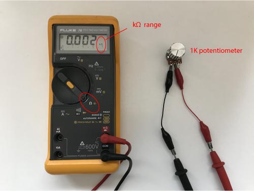
With most potentiometers, the wiper is located on the middle pin. But if you have doubts or you want to know for sure, go get your multimeter and measure the resistance value between the pins.
Start by setting the resistance measurement range on your multimeter. It must be set higher than the resistance value indicated on the potentiometer (look for the value on the side or on the back).
If there is no resistance value to be found anywhere on your potentiometer, don’t worry, just choose a random resistance range on your multimeter. It is best to choose a small range to start with.
If you have set the range too low, the multimeter will indicate an error. To make the error disappear, gradually switch to a higher range until you can read a resistance value.
Now, turn the knob to somewhere in the middle of the potentiometer and measure the resistance between the pins. As there are three pins, you have three possible combinations. Check them all out.
Your measurement results should show that one of the measured values is a lot higher than the other two. The highest measurement value corresponds to the resistance between the two pins connected to both ends of the potentiometer.
So, now you have found both endpins, the remaining pin is the one connected to the wiper.
Step 2: Find out if the potentiometer’s total resistance value is still correct
Since you have already measured the total resistance value of the potentiometer, you just have to compare it with what is indicated as the resistance value on the side or back of the potentiometer.
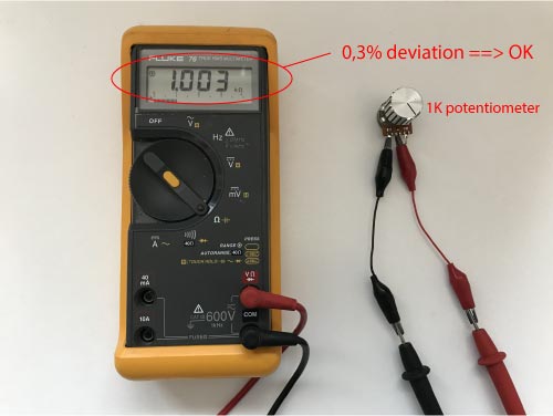
If you don’t find exactly the same value but something that is close by, don’t panic. Not all potentiometers are precision components. The tolerance can amount to 10% of the stated value.
But if the measured total resistance shows a larger deviation, this means that the potentiometer is in a bad condition and you should throw it away.
Step 3: Find out if the potentiometer’s resistance path is free from interruptions
The only thing left to do now is to check whether the resistance path has a smooth gradient.
Therefore, put the probes of your multimeter on one endpin of the potentiometer and the other on the wiper pin.
Now, slowly turn the wiper from one end to the other end and keep your eye on the multimeter display.
You should see the resistance value increase or decrease smoothly without large jumps up or down.
Be aware that there are also logarithmic potentiometers. So, if you think that the resistance value is increasing or decreasing too fast compared to the speed of rotation of the wiper, you could be testing an audio potentiometer with a logarithmic taper.
Which potentiometer types exist?
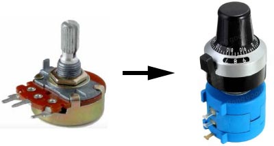
Rotary potentiometer
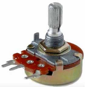
Photo by lainf / CC BY-SA 3.0
There are two design variations for a rotary potentiometer: single-turn and multi-turn. The most widely used industrial potentiometers are single-turn rotary potentiometers.
To move along the entire resistance range, single-turn potentiometers need to rotate less than 360°, while multi-turn potentiometers need to make multiple revolutions (e.g. 5, 10, 20, or 25 turns).
Due to their longer resistance path, multi-turn potentiometers have a higher resolution than single-turn potentiometers and are therefore much more accurate. The more complex design, however, also ensures that multi-turn potentiometers are more expensive.
Slide potentiometer
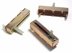
Photo by Omegatron / CC BY-SA 3.0
Unlike the rotary potentiometer, where the wiper performs a circular motion, the wiper of a slide potentiometer moves along a rectangular strip of resistance material in a straight line.
Because this potentiometer requires a large longitudinal opening for passage of the slider, there is a greater risk of dust and moisture getting caught between the sliding contacts and the resistance element. This causes more noise and even an interruption of the output signal.
Brushes or overlapping plastic foils covering that large opening can prevent dust from getting into the potentiometer but the risk is never excluded.
What materials are potentiometers made of?
Wirewound potentiometer
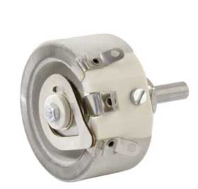
A wirewound potentiometer is made by wrapping a resistance wire, usually nickel chrome, around a ceramic, plastic, or glass
Usually, nickel-chromium is used as the resistance wire because this material has a very
Carbon film potentiometer
A carbon film potentiometer consists of a thin layer of carbon composite ink,
Cermet potentiometer
Cermet (
Plastic film potentiometer
The plastic film is sometimes also referred to as conductive plastic. The resistance element is composed of plastic resin such as epoxy, polyesters, improved phenolics, or polyamides to which carbon powder is added. The carbon grain size of about 0.01 μm determines the potentiometer resolution. The mixture is applied in a thick layer to a ceramic or plastic substrate using screen-printing methods and is then hardened in an oven.
How can a potentiometer be made more sensitive?
To answer this question, I must first explain the concept of a potential gradient.
If you connect a potentiometer to a voltage source, there will be a voltage V across its total resistance between pins 1 and 3.
If pin 1 is connected to ground, the potential at pin 1 will be zero volts, while the potential at pin 3 will be equal to the potential V of the voltage source.
Halfway the linear resistance path, the potential will be half the potential of the voltage source, i.e. V/2.

So you see that the potential is gradually increasing over the full length of the resistance path, just like a gradient.
The potential gradient is the rate of change of potential with respect to distance.
This means that:
The potential gradient is constant for a given potentiometer connected to a fixed potential.
Let’s put some numbers in that formula.
Say that the potential across the resistance path is 10V and that its length is 5 cm. The potential gradient then amounts to 2 V/cm.
This means that the output of the potentiometer increases by 2 V when we move the wiper 1 cm along the resistance path.
To obtain a potentiometer that is more sensitive, we need to reduce the potential gradient so that the change in output is smaller for the same wiper movement.
This way we can vary the output voltage in smaller steps.
How can we reduce the potential gradient?
Well, looking at the formula, there are two ways to do that.
- We can increase the length of the resistance path.
- We can decrease the potential across the total resistance path of the potentiometer.
Increasing the length of the resistance path cannot be done with a given potentiometer. So, if we want to follow this method, we will have to swap the potentiometer for another one with a longer resistance path, like e.g. a multiturn potentiometer.
Decreasing the potential across the total resistance path can be done with a given potentiometer by putting a resistor in series with the potentiometer as shown in the drawing below.
Depending on the resistance value of the added resistor, the potential gradient will be reduced to a greater or lesser extent. In the example shown, the potential gradient will be halved by choosing a resistor with the same resistance value as the potentiometer.

Can a potentiometer be repaired?
Due to the many devices nowadays using a digital volume control, many people are no longer used to hearing the sound of a scratchy potentiometer. If you are one of them, do not think that you are missing out on something, it is just terrible.
Looking at what causes a potentiometer to be scratchy, we can list a number of reasons.
First of all, there is the problem of dust entering the potentiometer. Especially slider potentiometers are prone to dust because it is more difficult to seal the large longitudinal opening for passage of the slider. Dust can cause the wiper to lose contact with the resistive element, thereby interrupting the output signal.
Secondly, oxidation on the wiper and the sliding track due to moist air will increase the contact resistance between the wiper, the resistive element, and the sliding track, thereby weakening the output signal.
And third, traces of wear on the resistive element due to contact with the wiper causes the resistance value to fluctuate during the
So, what can be done about it?
To begin with, you must always try to first remove the dust and corrosion from the potentiometer. You can try to do this without having to disassemble it.
Warning!
Before starting the repair, you must unplug the device from the mains and remove all batteries (if present). Failure to comply with this precaution could result in serious injury or property damage.
Look for small openings on the side or around the connection pins. Along these openings, you can blow out any dust with compressed air. Then you spray some contact cleaning fluid through the same openings. Try to aim in all possible directions to make sure the internals are all wetted.
Contact cleaner is a chemical product based on solvents. It dries quickly, leaves no residue, and removes all oil, dirt, condensation, and encrustations caused by oxidation.
Wait for a few minutes to be sure that the solvents are evaporated and then put the power supply back on.
You can now test your potentiometer and see if your efforts have been rewarded.
If the problem is not yet resolved, the oxidation may be more severe than expected or there may be wear on the resistive element. The only solution to that is opening up the potentiometer.
Don’t forget to switch the power supply back off and take the batteries out before dismantling anything.
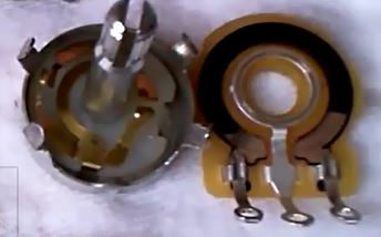
With the potentiometer open, check the sliding track and the contact points of the wiper for oxidation. If you see any oxidation, you can use a piece of very fine sandpaper (P1000 or higher) to sand it off.
Repairing the wear tracks on the resistive element caused by the wiper is nearly impossible without ruining the potentiometer. But what you could do is bend the fingers of the wiper a little bit inward or outward so they run on a fresh track of the resistive element. Be careful though not to break them off.
Before you reassemble the potentiometer make sure there is no dust left behind on the inside.
One last remark. If you would happen to have a completely sealed potentiometer, you cannot do anything of the above at all. In this case, you’ll have to replace the unit.
Related topics
Leave a Comment
Your email address will not be published. Fields marked with * are required.