DP Flow Transmitter Calibration: A Step-by-Step Guide
Differential pressure flow meters are widely used in the industry for the measurement of flow in a closed pipe.
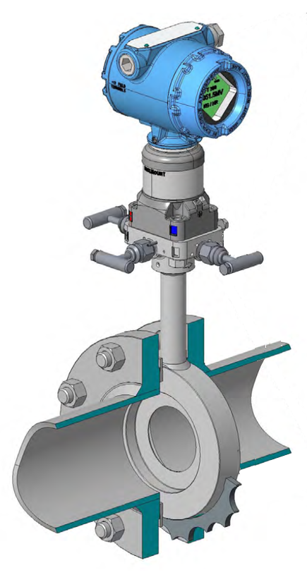
This kind of flowmeter consists of two parts:
The primary element
The differential pressure transmitter
The DP flow meter will calculate the flow rate by measuring the differential pressure across a primary element.
Various types of primary elements can be used to obtain differential pressure. Some of the most common primary elements are orifice plates, (averaging) pitot tubes, venturi tubes, and flow nozzles.
They all operate on the same principle that the flow through the primary element is proportional to the differential pressure across the element.
Although DP type flow transmitters are known for their high performance and reliability, they will need a recalibration from time to time.
For the purpose of the calibration procedure that we will describe further on, we will consider a DP transmitter with an orifice plate as the primary element.
To be clear, we are not going to calibrate the entire flow measurement, but only the DP flow transmitter. To calibrate the complete flow measurement, the primary element and the DP flow transmitter would have to be demounted and then installed on a flow test bench to be compared with a reference flow meter. This is something that is typically done in a calibration lab.
Relationship between Flow Rate and Differential Pressure
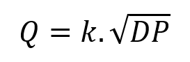
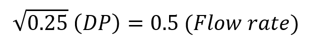
The following equation describes the relationship between flow rate and differential pressure:
where Q is the volumetric flow rate, k is a constant, DP is the differential pressure, and the square root function represents the relationship between velocity and pressure.
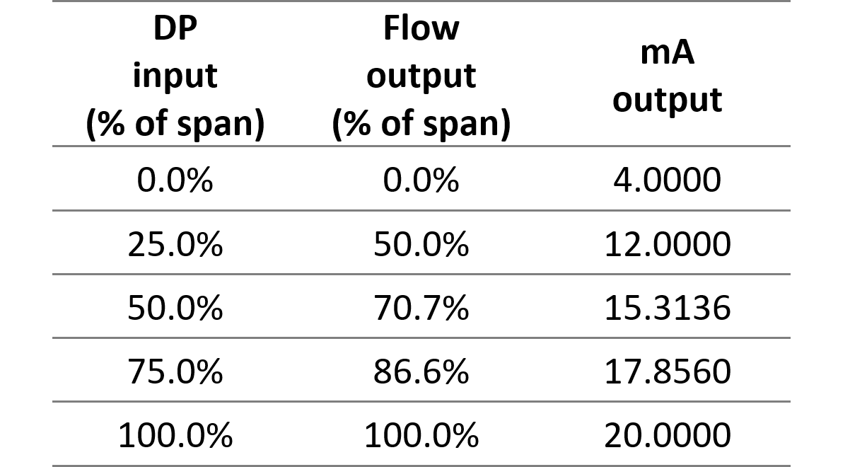
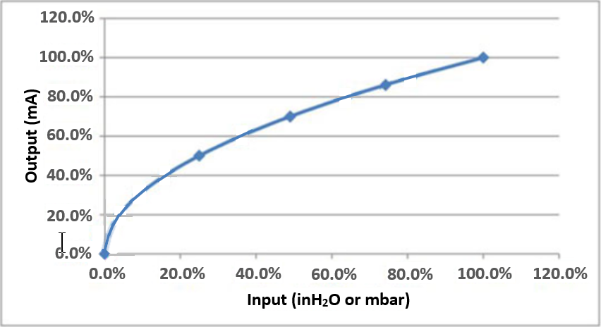
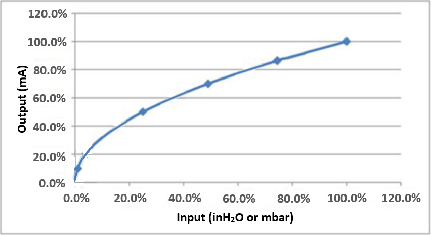
From this equation, we can see that an increase in differential pressure will result in an increase in flow rate. However, the relationship between flow rate and differential pressure is not linear but square-rooted, as you can see from the diagram below.
A 25% increase in differential pressure will result in a 50% increase in flow rate.
Low-flow Cut-off
Let’s have another look at the DP vs Flow curve above. Check in particular how the curve behaves in the region around the origin.
In this region, the slightest change in differential pressure causes the flow to change rapidly. A little noise on the DP signal gets multiplied by a factor of 10 or more on the flow signal.
This makes the flow signal very unstable and unreliable. Therefore, vendors will define a low-flow cut-off for the flow meter. That means that the output signal will be set to 4mA once the flow drops below 10%.
The low-flow cut-off is only present in DP transmitters with internal square root extraction. If the square rooting is done by the PLC/DCS, then the DP transmitter has a linear output and the low-flow cut-off should be programmed in the PLC/DCS.
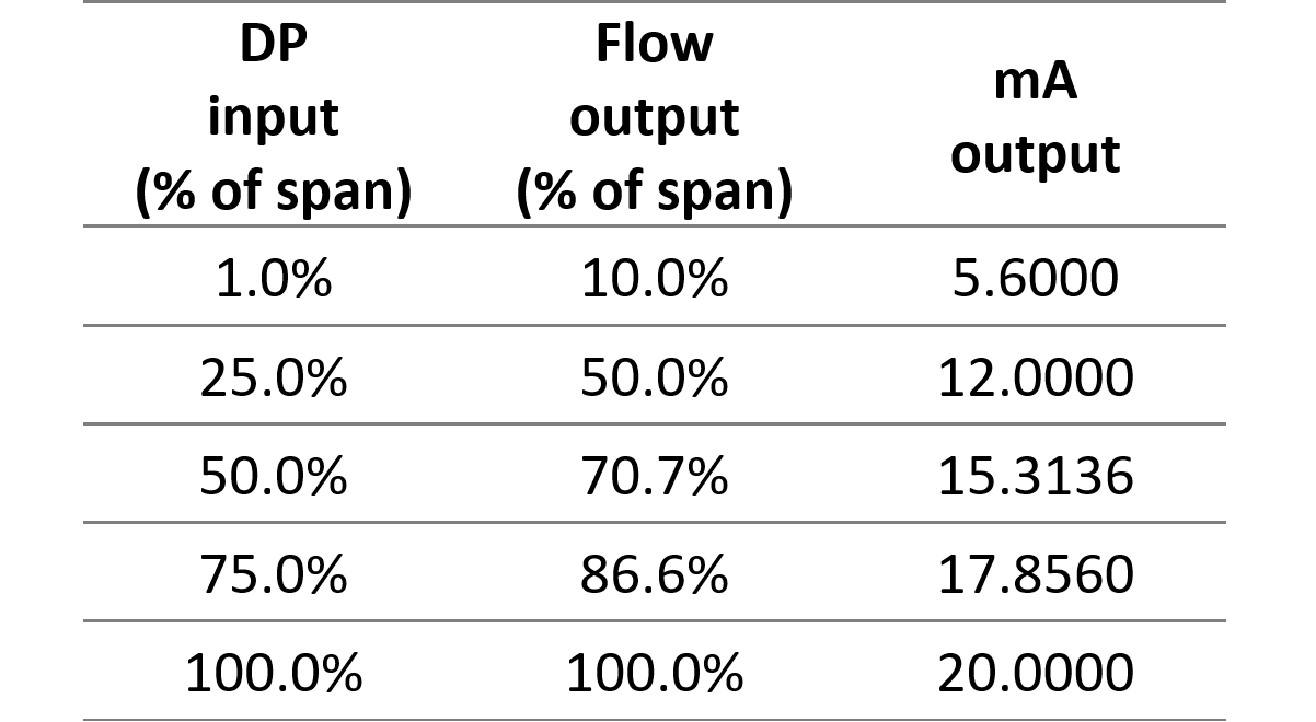
A low-flow cut-off at a flow rate of 10% corresponds to an output of 5.6 mA. So, between 4 and 5.6 mA there is no useful measurement possible because of too much inaccuracy.
All of that will have consequences on the calibration of our DP flow transmitter. For a typical five-point calibration of a transmitter with linear output, the test points would be 0, 25, 50, 75, and 100% of the flow rate. But, if the DP flow transmitter performs the square root calculation and a Low-Flow Cut-Off is considered, it has no sense to have a test point below 10% of the flow rate. So, the test points should be 10, 25, 50, 75, and 100% of the flow rate.
What are the tools needed to calibrate a DP type flow transmitter?
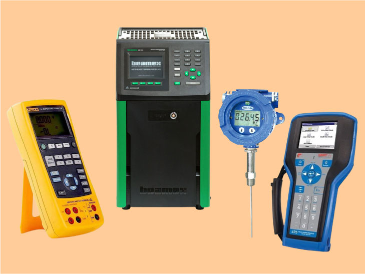
Besides the DP flow transmitter itself, we will need the below-mentioned tools to perform a calibration:
A calibrated pressure calibrator capable of indicating pressure in mmH2O, because here the DP transmitter for measuring flow has a range in mmH2O.
A calibrated pressure gauge of the appropriate range.
A 24Vdc power supply (if the pressure transmitter is not connected to the system and needs an external power supply)
A digital Multimeter
A HART communicator
Some important things to consider before starting the calibration of a DP-type flow transmitter
Check all the tools mentioned above. Check their calibration date’s validity and ensure they are charged one day before planning the job.
Obtain a work permit with all risk assessments performed.
Make sure you have the datasheet of the DP flowmeter when performing the calibration task.
Go through the C&E (Cause and Effect Matrix) and bypass all the interlocks present for the DP-type flow transmitter. Follow the proper bypass procedure and fill out all necessary interlock bypass requests.
Inform all involved process operators at the start of the calibration job.
The DP type flow transmitter calibration procedure
When all the preparatory work has been completed, we can now start calibrating the DP flow transmitter.
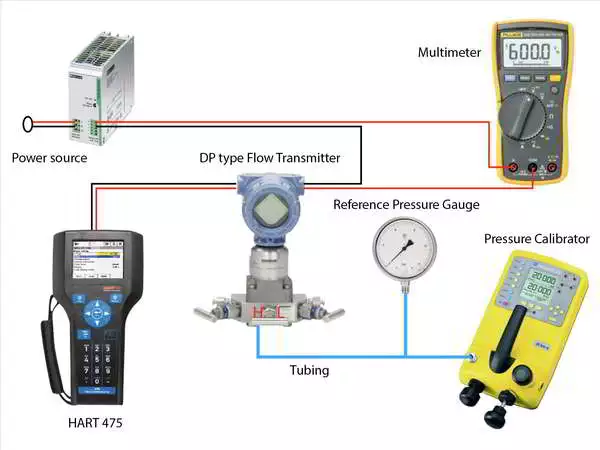
Arrange all the tools as shown in the above figure.
The DP-type power transmitter can be powered through the field cables connecting the DP transmitter to the system, or by using an external power supply shown in the figure.
If the differential pressure flow transmitter is in the field, then isolate the DP transmitter. Flush the differential pressure transmitter in a closed drain if it comes into contact with a dangerous process medium like a hazardous chemical.
Connect the power supply, the multimeter, and the DP flow transmitter in a series configuration. Make sure to connect the multimeter leads to the mA terminal and the common terminal.
Now connect the DP transmitter to the pressure calibrator using the appropriate tubing. Here we can use PU tubing because the pressure to be applied to the DP flow transmitter is in the mmH2O range.
Connect a precision pressure gauge of appropriate range to the pressure-generating device if for any reason this device would not display the generated pressure.
Prior to starting the calibration, it is necessary to determine whether the square root extraction takes place in the DP transmitter or in the PLC/DCS. The output value (mA) of the DP transmitter will depend on where this square root extraction occurs. So, check the datasheet or the configuration parameters of the DP transmitter to see if the transmitter does the square root extraction. A third option is to simulate 25% of the DP range with the pressure calibrator and look at the output (mA) of the DP transmitter:
If the output is about 12mA, the sqrt extraction is performed by the transmitter.
If the output is about 8mA, the sqrt extraction is performed by the PLC/DCS.
Let’s take an example to see what we can expect. Imagine a DP flow meter with the following ranges: * Flow range: 0 – 1000 m3/h * DP range: 0 – 5000 mmH2O We want to do a five-point calibration of the transmitter‘s mA output. Now there are 2 possibilities: the square root is done in the transmitter, or it’s done in the PLC/DCS. Let’s have a look at both possibilities.
If the transmitter performs the square root extraction, we have a mA output representing the flow rate. So since we want to calibrate the transmitter’s output, we will have to distribute our test points evenly over the output range. Considering what we said earlier about the inaccuracy at the low flow range, we will test for 10%, 25%, 50%, 75%, and 100% of the flow range. We will arrange these values in the table below and add the corresponding DP-values and mA-signals.
Test points
Flow (%)
Flow (m3/h)
DP (mmH2O)
Output (mA)
TP1
10 %
100
50
5,6
TP2
25 %
250
312.5
8
TP3
50 %
500
1250
12
TP4
75 %
750
2812.5
16
TP5
100 %
1000
5000
20
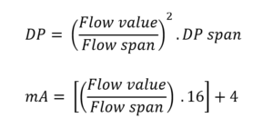
The values in the DP (mmH2O) and Output (mA) columns have been calculated with the following formulas:
Flow value = flow rate at the test point
Flow span = 1000
DP span = 5000
If the PLC/DCS performs the square root extraction, we have a mA output representing the measured DP. In this case, if we want the test points evenly distributed over the output, we will test for 0%, 25%, 50%, 75%, and 100% of the DP range. We will arrange these values in the table below and add the corresponding Flow values and mA-signals.
Test points
Flow (%)
DP (mmH2O)
Flow (m3/h)
Output (mA)
TP1
0 %
0
0
4
TP2
25 %
1250
500
8
TP3
50 %
2500
707,1
12
TP4
75 %
3750
866
16
TP5
100 %
5000
1000
20
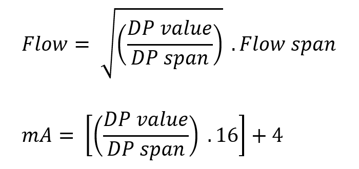
The values in the Flow (m3/h) and Output (mA) columns have been calculated with the following formulas:
DP value = DP at the test point
DP span = 5000
Flow span = 1000
Now that we know where the square root extraction is done and we have calculated our test points, we can start the validation procedure. We will do an ‘As Found’ test on all test points. This test is done for two reasons:
If this test proves that the instrument is still within the required accuracy for the application then we do not have to recalibrate it.
With this test, we will record the history of the device performance data. This will be helpful to decide if we need to shorten or prolong the calibration frequency.
We will use the following table for our ‘As Found’ test:
Test Points
Applied
Transmitter output
Error %reading
DP (mmH2O)
Flow (m3/h)
DP (mmH2O)
Flow (m3/h)
50
312,5
1250
2812,5
5000
2812,5
1250
312,5
50
I have filled in our test points based on a dp transmitter with square root extraction.
You can see that our test points are going in ascending order from minimum to maximum value and then in descending order back to minimum. This is important because the results can be different for the same test point when approached from below or from above. So, be very careful when approaching a test point not to overshoot it because if you have to come down again it will not give you the same result.
Start the validation procedure with zero pressure on the pressure calibrator and increase the pressure until you reach the pressure value of the first test point. Note down the reading from the pressure calibrator in the second column ‘Applied DP’ and the reading from the transmitter in the fifth column ‘Transmitter output Flow’. Similarly, apply the pressures of the other test points in the order they appear in the table. Note down the readings from the pressure calibrator and the transmitter in the appropriate columns. Every time you reach a new test point, the applied pressure value should remain stable for 30 seconds before reading the output value from the transmitter. If the pressure drops during these 30 seconds, then there is a leakage in the tubing or an issue with the pressure calibrating device. Identify the root cause and attend to it.
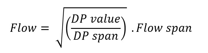
As the square root extraction is done by the transmitter, its output represents the flow rate. To calculate the error on the output, we will have to compare the measured flow rate with the applied flow rate. As we can only apply a DP, we will have to calculate the applied flow with the following formula:
Do this calculation for every test point and fill in the flow rates in the third column ‘Applied Flow’.
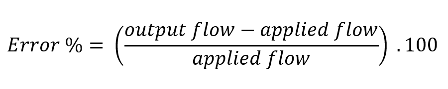
Now calculate the error % from the Flow values we got with the next formula:
If the calculated errors are all well within the required accuracy for the application, then the DP type flow transmitter is ok and should not be recalibrated. If the error obtained from the calculations is more than the required accuracy for the application then a calibration of the DP flow transmitter is needed.
A recalibration of a dp flow transmitter with internal square root extraction consists of a lower trim at the 10% flow point and a span trim at the 100% flow point. We can not do a zero trim for a transmitter with square root extraction because the zero point is too unstable. Any fluctuation in the input signal, no matter how small, is multiplied tenfold at the output. First, apply 1% DP on the input of the transmitter and check if this corresponds to 10% flow at the output. If this is not ok then start a lower trim at the 1% input / 10% output level (not zero) using the HART communicator.
Now check the 100% flow point by applying the 100% DP pressure to the input of the transmitter. If the reading does not indicate 100% flow, perform a span trim using the HART calibrator.
When the lower trim and span trim is completed, the transmitter is calibrated. To check whether everything went well and whether the transmitter will measure correctly, we will now do an ‘As Left’ verification. Repeat the procedure from step 9 to the end. Set up the ‘As Left’ table with the same test points as those from the ‘As Found’ table. If the calculated errors from the ‘As Left’ table fall within the required accuracy for the application, the calibration is successful.
All that remains is to return the transmitter to service. Inform the operator that the DP flow transmitter calibration job is finished and remove any interlock bypasses you placed at the start.
Why a differential pressure flow transmitter needs to be calibrated
All instruments need to be recalibrated over time. A DP flow meter makes no exception to that rule. A slight progressive accuracy degradation also called drift is the reason for these recalibrations. Drift is caused by the aging of the material and the wear and tear on mechanical and electronic components.
The sensor of the transmitter can be considered as a mechanical component. During its lifetime, this sensor will be subjected to constant pressure fluctuations, causing it to be repeatedly tensioned and released. This can eventually lead to small deformations causing small inaccuracies. The same can happen to the diaphragm that separates the sensor from the process, the body of the pressure transmitter, …
The transmitter’s electronics also age under the influence of temperature fluctuations, humidity, mechanical shock, or vibration… which changes the processing of signals over time.
To compensate for all these small changes, we occasionally need to recalibrate the transmitter.
Factors affecting the DP flow transmitter calibration frequency
Process functionality and importance of the flow measurement When the differential pressure flow meter is part of a flow control loop, it will be more important than if it is only used for indicating flow on the control panel. More important measurements should be calibrated more often.
Operating conditions If the DP transmitter is frequently required to operate close to its operating limits, the deviation of the output signal will be greater over time.
The quality of the instrument Differential pressure transmitters fabricated with the latest technology, using high-standard components will drift much less than lower-quality instruments. Therefore their calibration interval will be longer. The best ones can reach a calibration interval of 5 to 10 years.
Regulations and standards Because regulations and standards don’t know what type of instrument you are using and what your application is, they do not give you the exact calibration frequency for the instrument, but they do give you a measurement accuracy that you need to achieve. Based on that information, you then have to determine for yourself which calibration interval will be required.
Manufacturers recommendations If you bought an instrument from a reputable manufacturer, the manual should normally state the calibration interval. Of course, this is only a recommendation from the manufacturer who does not know what application you are using the instrument for. It gives you the ideal calibration interval for using the instrument under normal operating conditions. If you have no experience with your application, this is a good value to start with.
How often should you perform a DP flow transmitter calibration?
When you install a DP flow meter on a new application, you want to have an idea of when you will need to recalibrate it. Well, there is a way to determine the calibration interval by calculation.
I’ll show you how to do it.
First, you need to decide on the accuracy required for your application, and by required accuracy I don’t mean the reference accuracy of the DP transmitter but the total performance of the installed measurement.
Errors that occur through ambient temperature changes and high static pressure on the differential pressure transmitter should therefore be taken into account.
Generally, for pressure transmitters, the total installed performance will be between 0,5 and 2,0% of calibrated span. Here is a short list of applications with their required installed performance to help you make your choice:
● Plant safety and efficiency control
0,5%
● Regulatory control
1,0%
● Supervisory control
1,5%
● Monitoring
2,0%
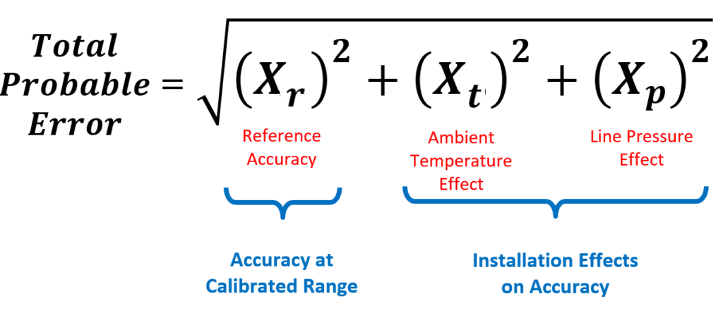
Once you have determined the installed performance, I want you to calculate the total probable error with this formula:
To populate the equation you will need to dive into the published specifications of the differential pressure transmitter.
The reference accuracy will be given in % of span. Find that number and put it in the formula.
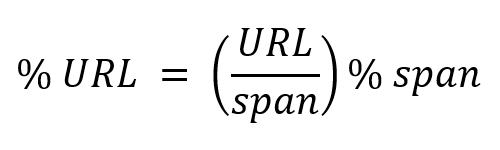
The ambient temperature effect can be given with a formula where a part of it is expressed in the unit ‘% URL’ and another part in the unit ‘% span’. When this is the case, you should convert the unit ‘% URL’ to the unit ‘% span’ as follows:
The static pressure effect also called the line pressure effect, could be given as a % of reading. Because we have to convert everything to % of span, we will simply consider the pressure reading at full span. This way, we can just keep the percentage value and replace the unit ‘% of reading’ with ‘% of span’.
Now, populate the above formula with the 3 results we have found and calculate the Total Probable Error.
The next thing to do is to search for the stability specification of the output. This will be given as a % of URL for a number of years, meaning that the instrument will lose accuracy at a certain % of URL over the stated number of years.
You should now convert the stability specification to engineering units, like e.g. inH2O, by replacing URL with its pressure value. This gives the stability in engineering units over a number of years. From this, you can calculate the stability per month instead of over a number of years.
Finally, you have to convert the required accuracy for your application and the total probable error to engineering units by replacing the word span with the value of the span.
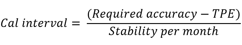
By using the following formula with the engineering units, you will find the calibration interval in months.
Get a better grip on your process with more accurate pressure measurements
Pressure calibration is something that needs to be done from time to time to keep your process running smoothly.
Anyone who is professionally involved with instrumentation will have experienced that measurement signals can deviate over time.
To avoid this deviation, pressure transmitters must be calibrated regularly.
This article will explain how to perform such a calibration.
What is pressure calibration?
Every pressure transmitter senses the pressure and generates an output signal per the design of the pressure sensor’s electronics.
Unfortunately, this pressure output signal will not be accurate forever.
After a certain time, the response of the pressure transmitter will change. This deterioration goes so slow it cannot be felt or visualized as a trend in many cases. Consequently, the process will get affected due to incorrect pressure values.
To overcome this problem, regular preventive maintenance of the pressure transmitter is required, or when any issue is suspected in the pressure transmitter. One of these preventive maintenance actions is the calibration of the pressure transmitter.
During the pressure calibration procedure, actual pressure is applied to the pressure transmitter using a very precise and well-known pressure source. If a problem is found, appropriate action is taken to correct the transmitter output.
After proper calibration of the pressure transmitter, the pressure transmitter electronics will provide an accurate output corresponding to the pressure detected by the pressure sensor.
Things to consider before calibrating a pressure transmitter
Before you start calibrating a pressure transmitter, some basic, but very important things need to be taken care of. It is better to prepare a checklist to prevent problems.
Here are the four things to consider:
Check the Interlocks associated with the pressure transmitter. If any Interlocks are there, then bypassing the interlock with a proper interlock bypass procedure is a must.
Check whether the pressure transmitter is used for controlling a control valve. If a control valve is controlled by the pressure transmitter in auto mode, switch the control loop to manual mode. During calibration, the pressure values will vary and if the control valve is in auto mode, it will start to move. This unwanted movement of the control valve will adversely affect the process.
Also, check whether the pressure value is used by other parts of the plant. If the pressure values of the pressure transmitter under calibration are used by other parts of the plant, inform the relevant operators to avoid problems.
Some critical pressure transmitters could be configured in a text messaging system. That system will send a text message to predefined phone numbers when there is a high or low-pressure reading. So, inform those people if such a possibility exists to avoid panic situations.
Tools and tackles needed for the pressure transmitter calibration job
A digital multimeter capable of measuring DC voltage and milliampere.
A pressure gauge with a range that is 1.5 times greater than that of the pressure transmitter.
A pressure-generating device such as a pressure pump, pressure calibrator, or dead weight tester, depending on the range of the pressure transmitter.
A HART communicator
Both 1/4″ and 1/2″ temporary tubes.
Various fittings of different sizes for connecting the temporary tube to the pressure transmitter.
Make sure the digital multimeter, HART communicator, and pressure-generating device are calibrated. The digital multimeter and the pressure-generating device must have a greater accuracy (minimum 4 times) than the accuracy required by the pressure transmitter. The pressure gauge must be calibrated with the main calibration device which is 4 times more accurate than the pressure transmitter.
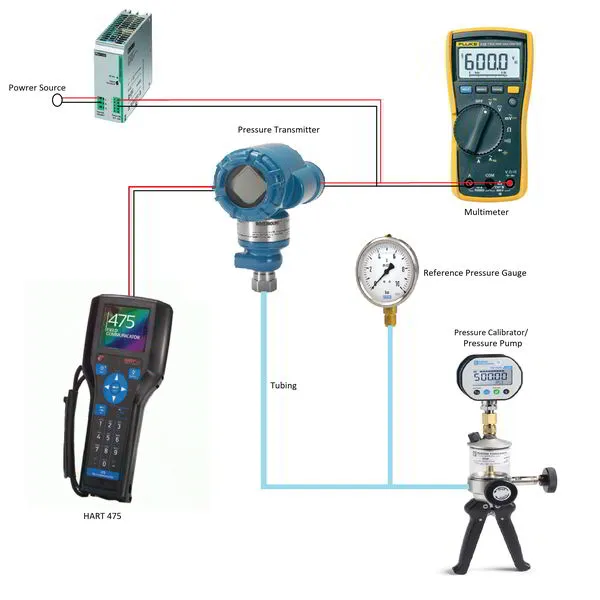
Pressure transmitter calibration procedure with pressure calibrator
For this calibration, we will use a hand pump to provide the test pressure.
Both pneumatic and hydraulic hand pumps are available. The choice between the two depends on the pressure you want to test at:
Pneumatic hand pumps can be used up to about 600psi (41bar)
Hydraulic hand pumps operate at pressures up to approximately 10000psi (690bar)
Below mentioned steps can be followed to do the calibration of a pressure transmitter:
Obtain a proper permit to work and do a proper risk assessment.
Bypass all interlocks with a proper interlock bypass procedure.
Put the control valve or ON-OFF valve in manual mode if any control valve or ON-OFF valve is being controlled by the pressure transmitter to be calibrated.
Inform all the operators (also at other parts of the plant) who are using the pressure transmitter signal and disable the alert system, if any exists.
Ask the operation department to isolate the root valve and put a proper isolation tag on the root valve for identification purposes.
Now the pressure transmitter needs to be drained for removing the material between the root valve and the pressure transmitter. If the pressure transmitter is used for measuring the pressure of a fluid that is toxic, flammable, or dangerous to humans or the environment, then do an arrangement for a closed drain. If the pressure transmitter is used for a safe fluid like regular water or air, then we can directly open the pressure transmitter to the atmosphere.
After the material between the root valve and the pressure transmitter is removed, open the pressure transmitter to the atmosphere. We can remove the vent plugs from the vent ports behind the valve manifold. In this condition, the pressure transmitter should show 0 kg/cm2 or 0 psi depending on the unit configured. This is the case for a gauge pressure transmitter. An absolute pressure transmitter will show 1 kg/cm2 or 14.696 psi depending upon the type of unit configured. This step helps to check the pressure transmitter’s response at atmospheric pressure conditions.
Now we need to check the response of the pressure transmitter with actual pressure. So, connect the hand pump to the pressure transmitter. Use proper fittings that do not cause damage to the pressure transmitter and do not leak while pressurizing the pressure transmitter. Configure the pressure range of the pressure generator to the same measurement range as the pressure transmitter.
Also, connect a pressure gauge with the correct range (usually 1.5 times that of the pressure transmitter) to the hand pump and the pressure transmitter. This is done to double-check the pressure exerted by the hand pump.
Connect a digital multimeter to the 24 VDC supply loop of the pressure transmitter if the pressure transmitter is operating at 4 mA to 20 mA. If the Foundation Fieldbus protocol is used, you do not need to connect a digital multimeter.
Connect the HART communicator to the pressure transmitter.
Check the measuring range of the transmitter and calculate 5 calibration test points. These calibration points will correspond to 0%, 25%, 50%, 75%, and 100% of the range. You can find the range by looking into the configuration settings of the transmitter or finding it on the datasheet. The 5 test points can easily be calculated with this calibration test points calculator.
Use the hand pump to start applying pressure to the transmitter. First, apply a 0% value. Check the value on the hand pump, the pressure transmitter, and the double-check gauge. All the values should be equal to the 0% value. Now confirm the value indicated on the operator’s HMI or the system. If any discrepancy is found, then troubleshoot it. In many cases, the issue is a value mismatch between the field and the HMI. There could be many reasons for this difference. Some reasons are listed below:
The range of the pressure transmitter is different from the range configured in the system. For example, the range of the transmitter is 0 to 100, while the range in the system is 0 to 50. So when the field device shows 50, the system shows only 25. Changing the range to the correct one will help solve this problem.
Instead of 4 to 20 mA, a range of 0 to 20 mA or some other range is sometimes configured in the field. But in the system, the range is 4 to 20 mA. So due to the difference in the mA range, the value will also be different. Or on the system side, the mA range is incorrect according to the datasheet. Changing the incorrect mA range to the correct mA range can solve this problem.
The transmitter is having a pressure-sensing problem. So, calibration is needed.
If an intermediate system is used to transfer the data, the range may also be misconfigured in that system. Often data is passed from the ESD control system to the DCS. So due to incorrect range configuration on either side, the value will be different.
Apply 25%, 50%, 75%, and 100% pressure values to the pressure transmitter. Wait a few seconds after applying the value so that the system becomes stable at that point. Check for leaks in between, if the readings do not match, or if the pressure is unstable. Record all the respective measured values in the calibration sheet.
Similarly, start from 100% by applying descending values in 25% increments and record all measured values.
Calculate the error% with the formula : (measured value – reference value) / reference value *100
If the error% is within the limits mentioned in the datasheet, then the pressure transmitter is ok.
If the error% is greater than the limit, then zero and span calibration is needed.
For a zero calibration, use the hand pump to apply the 0% of range value. Go to the calibration menu in the HART communicator and press the “Zero Trim” button. Wait for a few seconds till a success message is displayed.
Use the hand pump to apply the 100% of range value. Again, go to the calibration menu in the HART communicator and press the “Span Trim” button. Wait for a few seconds till a success message is displayed. (Some old transmitters have a zero and span setting screw. So, set zero and span from the screws one by one after applying the respective pressures)
After the pressure transmitter has been adjusted, it is necessary to reverify it. So, use the hand pump again to apply 0%, 25%, 50%, 75%, and 100% of range values. Note down all the values as you did previously. Also, check the values in decreasing order in steps of 25%.
Again, calculate the error%. The error% should be within the maximum allowable limit. If the error% is still too high, then do the calibration of the pressure transmitter one more time. Follow all the steps from step 18 onwards one more time.
If the error% still exceeds the limits, the pressure transmitter must be replaced.
If the calibration was successful, apply a calibration sticker to the pressure transmitter.
Restore all the bypassed interlocks after informing the process operators. If the loop is still in manual mode, ask them to put the loop back in auto mode. Inform other plants about the completion of the calibration job. Also, restore the messaging system if changes have been made or notify all involved persons of the completion of the pressure calibration.
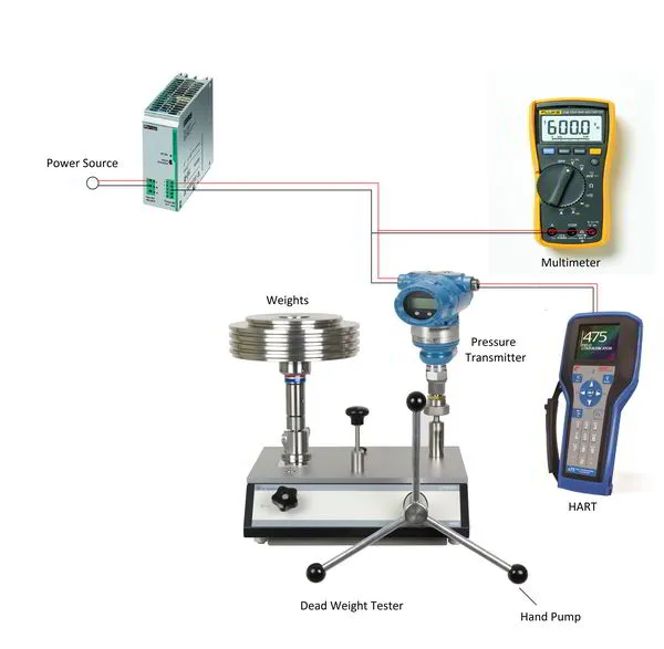
Pressure transmitter calibration procedure with dead weight tester
A dead weight tester is generally used in calibration laboratories. Dead weight testers have 5 to 10 times higher accuracy than a pressure calibrator or a pressure pump.
The accuracy to be obtained from a dead weight tester is about 0,006% of reading.
With a dead weight tester, discs with a very accurate weight are stacked on top of a piston that is filled with fluid. The piston converts the mass of the discs into an extremely precise fluid pressure.
Different types of fluids are available. Some dead weight testers work with air, others with oil or water. The choice of fluid depends on the test pressure that the dead weight tester must be able to supply.
Broadly speaking, the choice comes down to this:
air: up to 14MPa (140bar)
water: up to 70MPa (700bar)
oil: up to 140MPa (1400bar)
Special hydraulic dead weight testers can even produce pressures up to 400MPa (4000bar) or more.
The steps below can be followed to perform the calibration of a pressure transmitter using a dead weight tester.
Attention: If the pressure transmitter is used to measure oxygen gas or any other chemical which can react adversely with the oil of the dead weight tester, then do not use the dead weight tester.
Set up the dead weight tester, pressure transmitter, 24Vdc power supply, HART communicator, and multimeter as in the picture above.
Before connecting the power supply directly to the pressure transmitter, check the output voltage and set it according to the requirements of the pressure transmitter. Use a 250 Ohm resistor in series in the case of a HART protocol pressure transmitter and a Foundation Fieldbus (FF) power module in the case of an FF-type pressure transmitter. Now, turn ON the power.
Check the oil level inside the dead weight tester.
Put the appropriate weight on the weight platform according to the dead weight tester’s chart showing weight versus pressure.
Use the hand pump to apply pressure until the weight on the weight platform begins to float between the red and blue lines.
Check the value on the pressure transmitter and note it down.
Check all values at 25% intervals, starting from 0% to 100%, and vice versa from 100% to 0%. This leads to a 5-points calibration. You can calculate the pressure value of these 5 test points by using our calibration test points calculator.
Calculate the error% as we did in the case of a pressure transmitter calibration using a pressure calibrator.
If the maximum value of the error% is more than the maximum allowable error%, perform a zero and span calibration.
Repeat step 7 and recalculate the error.
If the maximum error% is still greater than the allowable error, try a zero and span trim one more time. If the error remains too high, replace the pressure transmitter.
After calibration, gently clean the sensor unit of the pressure transmitter with a suitable cloth to remove the oil on the sensor side.
How to choose which calibration method to use?
The method of performing a pressure calibration is highly dependent on the desired accuracy of the pressure transmitter.
Hand pumps have a maximum accuracy of 0,1% of reading, dead weight testers go as far as 0,006% of reading.
Based on the fact that calibration equipment must be at least 4 times more accurate than the device to be calibrated, we arrive at the following conclusion:
with a hand pump, pressure transmitters can be calibrated that must be accurate to a maximum of 0.5%
with a dead weight tester, we can calibrate pressure transmitters to an accuracy of 0.025%
Pressure transmitters used in critical services or used for invoicing must have very high accuracy and should be calibrated with a dead weight tester.
If only a few of these high-accuracy applications need to be calibrated each year, it may be better to have this performed by an external test lab.
If the company has many of these demanding applications, it may be more cost-effective to purchase a dead weight tester and perform the tests in-house.
Keep in mind that for some applications it is required that the test lab is ISO/IEC 17025 accredited.
These high accuracies are not always necessary to control a process. Usually, the repeatability of the measurement is much more important. Many pressure transmitters for process controls only need an accuracy of 0.5% or 1% and can therefore be calibrated with a hand pump.
In addition to the two categories already mentioned, there is a third category of pressure transmitters where accuracy does not play a major role. These are the pressure transmitters that only serve as a visual indication of the process pressure. Just to have an idea of the pressure in the pipe or vessel. They only need an accuracy between 1% and 5%. In this case, it may not even be necessary to calibrate them.
Why does a pressure transmitter need to be calibrated?
A pressure transmitter has a diaphragm or pressure sensor assembly to measure the pressure and an electronic circuit to convert the sensor signal to an output signal.
A membrane or pressure sensor assembly is nothing more than a mechanical device, subject to mechanical stress, abrasion, chemicals, or degradation of the fill fluid. So, it is obvious that all this will have an impact on the electrical properties of the sensor, e.g. a change in capacitance or resistance, whatever measuring principle is used.
Also, the transmitter is installed in the field and is powered on for 24×7 hours. The electrical current constantly flowing through the electronic components will slightly alter the characteristics of these components over time. Temperature variations, moisture, and vibration will also add to the electronics’ aging. The output signal strength can vary depending on how the electronic components react to this aging effect.
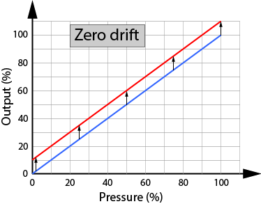
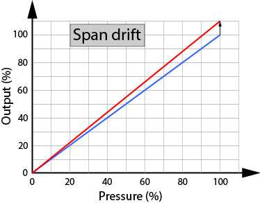
Under the influence of the above effects, the accuracy of a pressure transmitter will slowly deteriorate. This slow process of deterioration is called drift. There are two types of drift:
Zero drift: here the zero point will shift and the entire calibration curve moves up or down with it.
Span drift: here the shift is in the slope of the curve, and the zero point remains in place.
Zero drift is more common than Span drift.
So, over a period of time, the response of the transmitter will change because of the aging effects on the diaphragm as well as the electronic circuits. The measurement starts losing reliability, the process is less under control and safety becomes less guaranteed.
Hence it becomes necessary to validate the response of the transmitter. If during validation, any deviations are found, then calibration of the transmitter is necessary to avoid problems or measurement inaccuracies. A calibrated pressure transmitter can help increase process efficiency as well as prevent unwanted shutdowns and fatalities.
How often should you calibrate a pressure transmitter?
The calibration frequency of a pressure transmitter is determined by the process criticality. In general, pressure transmitters are calibrated with an interval of 3 to 5 years. In case of malfunction or incorrect operation, the pressure transmitter must be calibrated.
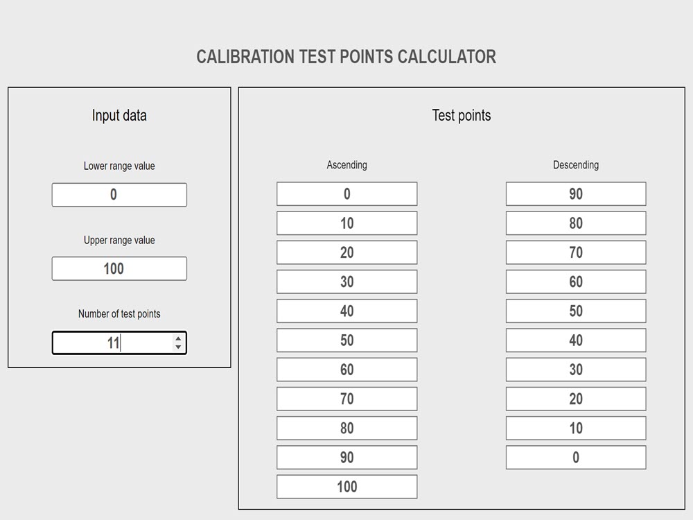
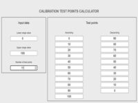
Calculate the test points for any kind of transmitter calibration
Before the calibration of a transmitter can be started, a number of test points must first be determined at which the measured value of the transmitter will be compared with the reference measurement.
The calibration test points calculator can calculate these test points for you based on the measuring range of the transmitter and the number of test points you want to test on.
How to use the calibration test points calculator
The calibration test points calculator consists of 2 parts: on the left is the input data part and on the right is the test points part.
Only the input data part needs to be filled in by you. The results will appear in the test points section after completing all three input data fields. Make sure to tap ENTER or TAB or just click outside the input fields to start the calculation.
To start a new calculation, simply change the value of the input data entered.
Lower range value
This is the lower limit of the transmitter’s set range. Example: The range of a temperature transmitter is set between -20°C and +70°C. Enter -20 as the lower range value.
Upper range value
This is the upper limit of the transmitter’s set range. Example: The range of a pressure transmitter is set between 50 bar and 100 bar. Enter 100 as the upper range value.
Number of test points
Enter the number of points at which you want to test the transmitter. The entered number must not be less than 2. When you enter a minus sign or a plus sign, it will be removed immediately. Decimal numbers are also not accepted.
Procedures for calibration of transmitters with RTD or Thermocouple sensors
Temperature transmitters are in use across all industries. Given the name, it is clear that a temperature transmitter transmits the temperature value it gets from the primary temperature sensing element.
The industrial primary sensing elements are mostly RTDs (Resistance Temperature Detector) and thermocouples. The output from an RTD is in terms of resistance, while a thermocouple’s output signal is in millivolts.
The temperature transmitter receives the signal from an RTD or a thermocouple. The transmitter evaluates the signal and converts it into an output signal like 4 to 20 mA, Foundation Fieldbus, Profibus PA, or any other type of signal like wireless. Mostly 4 to 20 mA and Foundation Fieldbus output signals are used in industries.
A temperature transmitter consists of electronic circuits. Usually, the performance of electronic circuits deteriorates with time. When the performance of the temperature transmitter deteriorates with time, it may start producing inaccurate readings. The temperature readings we get may be unreliable.
In the field of instrumentation, this slow deterioration of accuracy is called ‘drift’. Due to drift, the output of the temperature transmitter becomes inaccurate. For this purpose, we need to calibrate the temperature transmitter at regular intervals or when its output seems incorrect.
Temperature sensors like RTDs or thermocouples are exposed to high and low temperatures as per the applications. Due to the effect of varying temperatures, the material of the sensor also degrades with time. This degradation affects the sensor’s response and accuracy.
Thus, the validation of the sensors is also essential for getting accurate temperature measurements.
How do we approach a temperature calibration?
We already discussed that temperature transmitters can accept input from an RTD or a thermocouple.
The outputs of temperature transmitters can also be in many forms like 4 to 20 mA or Foundation Fieldbus signal (many others exist but these two are the most widely used, so we will consider only these two).
With two different input sensors and two different output signals, there are four possible combinations of temperature transmitters:
RTD with 4 – 20 mA HART transmitter
Thermocouple with 4 – 20 mA HART transmitter
RTD with Foundation Fieldbus transmitter
Thermocouple with Foundation Fieldbus transmitter
Temperature transmitters can also be compact (with the transmitter in the head of the temperature probe) or remote (with the transmitter at a distance away from the probe).
Usually, temperature measurements with compact transmitters will be completely demounted and calibrated in the workshop. In contrast, for measurements with remote transmitters, the sensor will be calibrated in the workshop and the transmitter is calibrated in the plant.
We will split the calibration procedure into two parts:
First, we will validate the RTD or thermocouple in the workshop.
Second, we will calibrate the temperature transmitter in the plant.
RTDs or thermocouples are validated in the workshop because they are difficult to validate in the plant for various reasons. The most important reason is that they need to be checked at different calibration temperatures. Generating different process temperatures in a running plant is impossible to do, and taking a temperature bath calibrator to the plant is impractical as these probes are often installed at places difficult to reach.
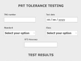
You may have noticed that we use the term validation instead of calibration for the temperature sensor. Validation (also called tolerance testing) means that we’re just going to check that the accuracy of the RTD or thermocouple is still within that sensor’s original accuracy class. If the sensor fails the test, we gonna have to replace it with a new one.
Calibration of a temperature sensor (also called characterization) is possible but more complicated and is usually only done for very accurate measurements. The characterization method compares the sensor to a highly accurate standard reference sensor. Calibration factors will then be calculated using methods like Callendar-Van Dusen for RTDs. These factors are entered into the transmitter to compensate for the inaccuracy of the sensor.
What tools are required to perform a temperature calibration?
To perform an accurate calibration, you need the right tools. There are many types of calibration tools. The ones we will be using are listed below:
Decade box
Portable digital calibrator or Beamex or Scandura
Digital multimeter
Temperature bath
HART communicator compatible with HART and Foundation Fieldbus devices
All the tools and tackles should be calibrated and the calibration date should not be due. Generally, a calibration sticker is attached to every tool for verification of its calibration status.
To perform highly accurate calibrations the temperature bath itself must be calibrated once a year.
The accuracy test or say calibration of these calibration tools is done by the National Test Laboratories. These laboratories have the most accurate instruments and are standard for the whole country.
For a perfect calibration, it is important that the accuracy of the calibration tools are at least 4 times to even 10 times more accurate than the device under test. If you want to calibrate a modern temperature transmitter, it is enough to use calibration equipment that is 4 times more accurate. That’s because present-day transmitters are already highly precise. Very old transmitters need to be calibrated with 10 times more accurate equipment.
Some points to be taken care of before starting a calibration
A few important points should be taken care of before proceeding with the job on the temperature transmitter:
Check if the transmitter has an interlock in the PLC or DCS. If any interlock is present, bypass the interlock with a proper interlock bypass procedure.
If any control valve is being controlled by the temperature value of the temperature transmitter, then ask the operation department to put the control valve in manual mode. Because during the calibration job, the temperature values will vary and if the control valve is in auto mode, the valve will make movements that will have an adverse effect on the process.
The temperature values may be used by other plants for some reason. So inform the respective plants that the temperature transmitter is going under calibration process and values will vary.
Some critical tags are configured in a text message or email system. Whenever there is a high or low value detected by the system on the particular tag, a message will be sent through text message or email. Inform all the configured contacts in the list about the calibration job on the temperature transmitter.
Validation procedure for an RTD sensor using a multimeter
To validate an RTD, we need to know some basic things.
We need to know the type of RTD, i.e. Pt100 or Pt1000, or any other type.
Check the datasheet or the transmitter’s configuration to find the temperature span of the transmitter.
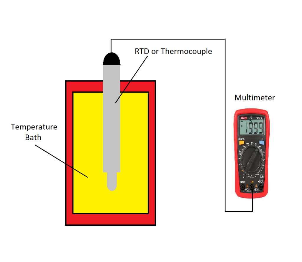
We will use a temperature bath and a multimeter in a setup like the one shown below.
Validation procedure:
Put the RTD into the temperature bath. Insert it up to the insertion length given in the datasheet.
Connect a multimeter to the RTD as per the configuration of the RTD, i.e. 2 wire, 3 wire, or 4 wire. And configure the multimeter to measure the resistance in Ohm.
Divide the span of the transmitter into 4 equal parts of 25% each. You now have 5 different test temperatures, i.e. 0%, 25%, 50%, 75%, and 100% of the span. If you don’t want to calculate these 5 test temperatures, you can use our automated calibration test points calculator.
Set the temperature bath to the 0% test point and wait until the temperature stabilizes. The 0% temperature should correspond to the lower range value of the transmitter. Stabilizing may take several minutes. If readings remain unstable, then check the termination tightness. Due to loose connections, the resistance might vary.
When the temperature bath indicates that the temperature is stable, note the Ohm reading from the multimeter in the ‘Output Ohm’ column on the table below.
In the temperature vs resistance table for the particular RTD, look for the resistance value corresponding to the temperature indicated on the temperature bath. Note this resistance value in the ‘Desired Ohm’ column.
Repeat points 3 to 5 for the steps 25%, 50%, 75%, and 100% in ascending order.
Repeat points 3 to 5 for the steps 75%, 50%, 25%, and 0% in descending order.
Calculate the error from the readings in percentage as follows: [(Output Ohm – Desired Ohm) / Desired Ohm] * 100
The RTD is still ok if the maximum error is less than the value of the error which is desired for the process conditions. This value can be fetched from the datasheet of the RTD.
If the maximum error is more than the error value mentioned on the datasheet then the RTD should be immediately replaced.
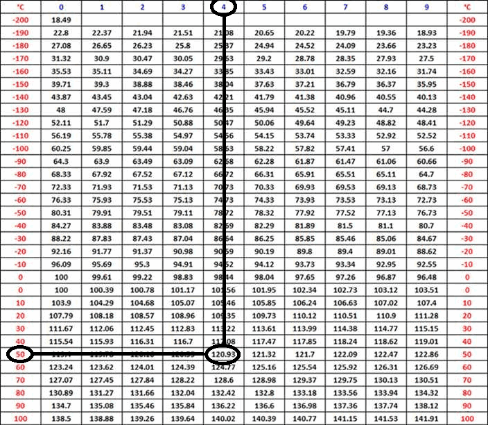
Use the table shown below for noting down the values. ‘Desired Ohm’ can be read from the particular RTD temperature vs resistance chart shown below this table. ‘Output Ohm’ is what you read from the multimeter. Error% is calculated with the formula from the above point 8.
To know the Ohm value of a particular type of RTD, you need the temperature vs resistance chart for that specific RTD. Here below you see an example of such a chart. Remember that a Pt100, a Pt1000, or any other RTD type has a different temperature vs resistance chart.
Example: For a temperature of 54°C, the RTD should have a resistance of 120.93 Ohm.
RTDs can also be checked by tolerance testing. Here’s an easy tool to do it:
Put the thermocouple into the temperature bath as we did for the RTD. Insert it up to the insertion length given in the datasheet.
Connect a multimeter to the thermocouple and configure the multimeter to measure the voltage in millivolts.
Set the temperature of the calibration bath to 0%, 25%, 50%, 75%, and 100% of the transmitter’s span. The 0% temperature should correspond to the lower range value of the transmitter. To calculate these 5 test temperatures, you can use our automated calibration test points calculator.
When the temperature bath indicates that the temperature is stable, note the millivolts reading from the multimeter in the ‘Output mV’ column on the table below.
In the temperature vs voltage table for the particular thermocouple, look for the millivolts value corresponding to the temperature indicated on the temperature bath. Note this millivolt value in the ‘Desired mV’ column.
Repeat points 3 to 5 for the steps 25%, 50%, 75%, and 100% in ascending order.
Repeat points 3 to 5 for the steps 75%, 50%, 25%, and 0% in descending order.
Calculate the error from the readings in percentage as follows: [(Output mV- Desired mV) / Desired mV] * 100
The thermocouple is still ok if the maximum error is less than the value of the error which is desired for the process conditions. This value can be fetched from the datasheet of the thermocouple.
If the maximum error is more than the error value mentioned on the datasheet then the thermocouple should be immediately replaced.
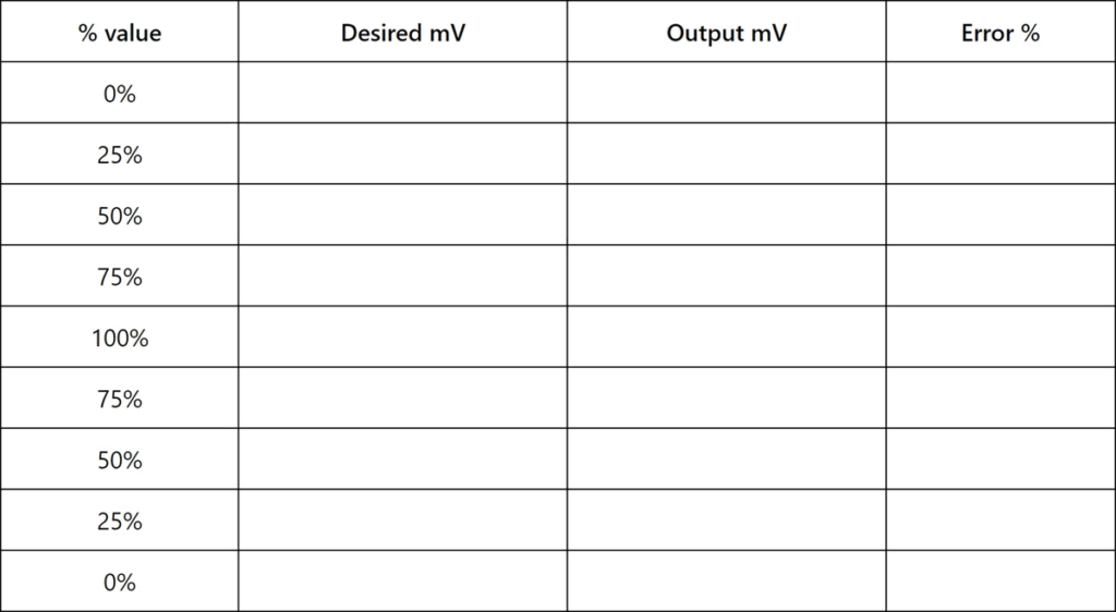
Use the table shown below for noting down the values. ‘Desired mV’ can be read from the particular thermocouple temperature vs voltage chart shown below this table. ‘Output mV’ is what you read from the multimeter. Error% is calculated with the formula from the above point 8.
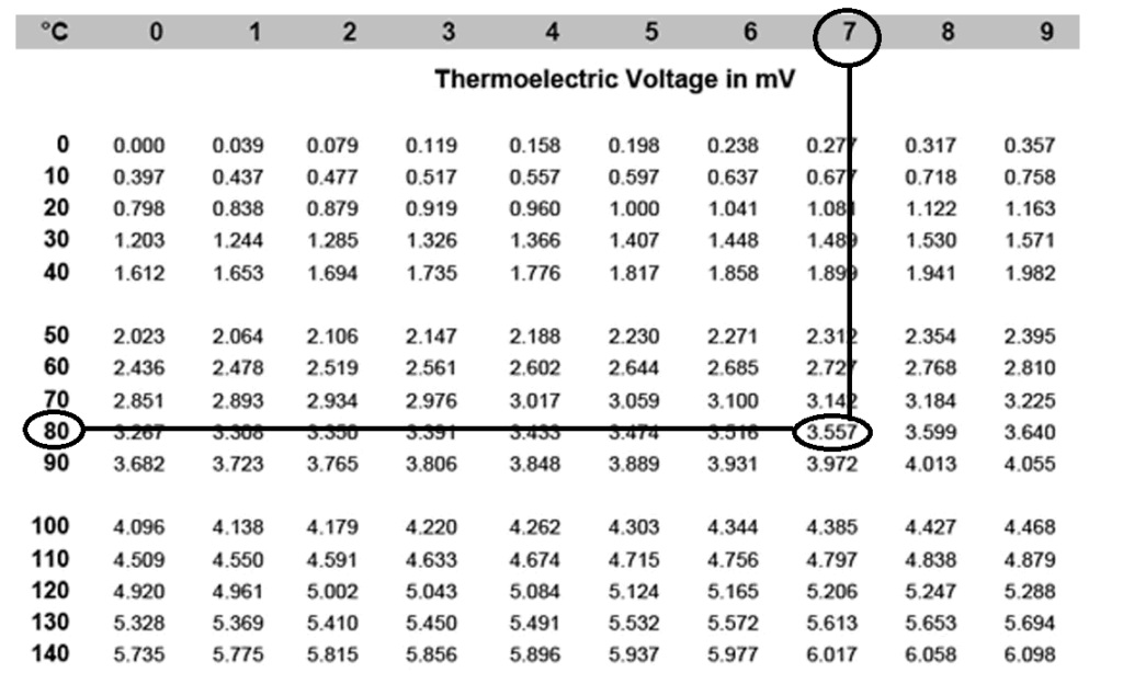
To know the mV value of a particular type of thermocouple, you need the temperature vs voltage chart for that specific thermocouple. Here below you see an example of such a chart. Remember that a type J, K, B, or any other thermocouple type has a different temperature vs voltage chart.
Example: For a temperature of 87°C, the thermocouple should produce a voltage of 3,557 mV.
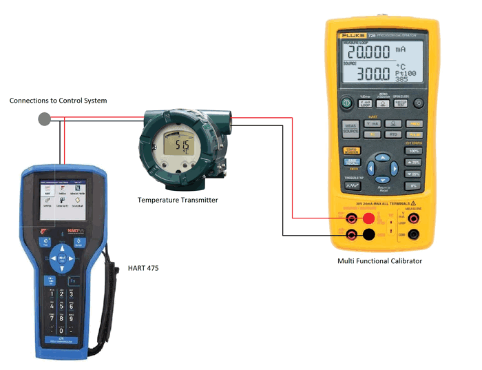
Calibration procedure for a temperature transmitter
We will do the calibration in the field with the transmitter still connected to the PLC or DCS. So, before starting the below procedure, don’t forget to take the control loop in manual and disable eventual interlocks in the system. Also, check if a copy of the signal is sent to other parts of the plant or if the tag is used in systems sending out text messages or emails. Inform the operator and any other people concerned about the ongoing calibration job.
Connect a multi-functional calibrator or any other device like a decade box, a Scandura, or a Beamex to the temperature transmitter.
Configure the calibrator according to the type of temperature sensor that is or will be connected to the transmitter. The output of the calibrator should be in ohms if the temperature sensing element is an RTD, or in mV when de sensing element is a thermocouple.
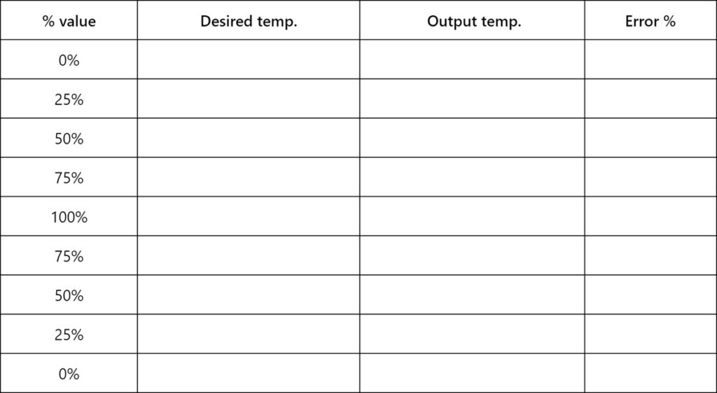
Apply the ohm or mV signals from the multi-functional calibrator to the temperature transmitter in steps of 25%, starting from 0% to 100%. To calculate these 5 test temperatures, you can use our automated calibration test points calculator. The 0% value corresponds to the lower range value (LRV) of the transmitter’s configured range. The 100% value corresponds to the upper range value (URV) of the transmitter’s configured range.
Note the applied temperature values from the calibrator (desired temp.) and the output signal from the temperature transmitter (output temp.) in the table below.
Similarly apply values in the downward direction in steps of 25%. Also, note these values in the table below. Confirm the values with the values in the HMI or DCS.
Calculate the error from the readings in percentage as follows: [(Output temp. – Desired temp.) / (URV – LRV)] * 100
The temperature transmitter is still ok if the maximum error is less than the value of the error which is desired for the process conditions. This value can be fetched from the datasheet of the transmitter.
If the maximum error is more than the error value mentioned on the datasheet then the temperature transmitter has to be calibrated.
To calibrate the temperature transmitter, first apply the 0% value from the calibrator. Do the zero trim of the transmitter using the HART communicator.
Then apply the 100% value from the calibrator and do the span trim of the transmitter using the HART communicator.
Now again check all the steps starting from step 3.
Restore the interlocks which are bypassed and ask the operator to put the control valve back in auto mode after job completion.
Inform all concerned persons about the completion of the activity.
What is the importance of calibrating temperature measurements?
Timely calibration of temperature measurements is essential in any industry. Knowing the exact temperature of the process improves process efficiency.
Suppose the temperature reading shows a lower temperature than the actual process temperature, then more energy is needed to maintain the temperature. This deviation can also damage the product due to overheating.
Inversely, if the temperature transmitter shows a higher temperature than the actual temperature, the product will get low heat, and the quality will not be up to the mark.
A calibrated temperature transmitter also helps to avoid unwanted trips due to disturbed plant parameters.
In some critical and hazardous process industries, inaccurate readings from the temperature transmitter can also put lives in danger.
Often, the performance of the temperature transmitter during plant run may not be accurate due to various reasons such as the environment. This environmental influence also changes the transmitter’s response over time and leads to deviations in the readings.
Performing the transmitter calibration will help eliminate the drift in readings and reduce the disastrous impact on productivity. Calibrating the instrument will also help to ensure that the processes will deliver desired results as per design.
Additionally, some machines should be protected against high temperatures, e.g. compressors, heaters… Additional heat or high temperatures will damage the machine or equipment.
Therefore, temperature transmitters should be calibrated at regular intervals.